
Korean PCB Manufacturers Panic-Buy Copper Clad Laminates as AI-Driven Supply-Demand Imbalance Intensifies
2026-05-14
In early May 2026, a printed circuit board (PCB) manufacturer in the Seoul metropolitan area placed pre-purchase orders worth 10 billion Korean won (approximately 50 million RMB) with two Chinese copper clad laminate (CCL) suppliers — more than five times its normal monthly usage. The company's CEO stated that the move was driven by concerns over supply disruptions, noting that delivery times had become uncertain. For the first time in over 20 years in the industry, the company faces the risk of production stoppages due to CCL shortages.
Currently, CCL lead times are generally being extended. For some high-end products, delivery times have increased from the original 2–4 weeks to over 6 weeks, leading to advance order locking and excessive stockpiling. According to data from the Korea Customs Service, the average import price of CCL in South Korea rose 74.5% year-on-year in March 2026, the highest since 2000.
CCL is a foundational material for PCB manufacturing, akin to the "highway foundation" for electronic products. AI servers, switches, optical modules, and liquid cooling systems impose higher demands on PCBs, driving downstream PCB manufacturers to accelerate capacity expansion. However, upstream CCL capacity expansion is lagging. Building new plants takes 18–36 months and involves resins, copper foil, fiberglass fabric, and high-end precision equipment, making it difficult to respond quickly to surging demand.
AI-related PCBs require 3–5 times the quantity of CCL compared to traditional servers, keeping CCL supply and demand consistently tight. Major global manufacturers have been raising prices intensively: Kingboard Laminates announced a 10% price increase on its entire FR-4 CCL and PP prepreg product lines on April 28, 2026 — its second increase in April and third of the year — with cumulative rises exceeding 40%. Taiwan Union Technology raised prices on high-end CCL by 20–40%. Elite Material and Iteq increased prices on high-grade materials by 10% in the second quarter. Mitsubishi Gas Chemical raised high-end CCL prices by 30% from April 1. Panasonic will increase prices across its full range by 15–30% starting in May. Domestic Chinese manufacturers such as ShengYi Technology, Nanya New Material, and Goldenmax International have followed with increases of 10–15%.
Upstream materials are also in tight supply. High-end fiberglass fabric (e.g., 1080) has been in short supply since 2025, with shortages extending to standard specifications in 2026. Inventories at Grace Fabric's Huangshi subsidiary have fallen below 10 days. High-end copper foil is constrained by a monopoly on core overseas equipment, limiting capacity expansion. High-end resin is in tight supply while ordinary resin is oversupplied, creating an "hourglass" structure in the supply chain.
The Shanxi Securities Research Institute noted that AI-driven demand for high-end CCL is highly sustainable, and the tight supply-demand situation is expected to persist through 2027 or even longer. If price increases continue at the current pace, a sheet of CCL originally priced at around 100 RMB could exceed 400 RMB after seven rounds of 10% increases — a price surge comparable to historical levels seen in fiber optic products. Although rising market expectations carry the risk of volatility, real demand for AI hardware continues to grow, and the fundamental industry logic has not reversed.
-----------------------------
Sources: DoNews.
Disclaimer: We respect originality and also value sharing; the copyright of text and images belongs to the original authors. The purpose of reprinting is to share more information, which does not represent the position of this account. If your rights are infringed, please contact us immediately for deletion. Thank you.
View More
AI Demand Drives CCL Market, Expected to Reach $21.5 Billion This Year
2026-05-11
Despite Taiwanese manufacturers holding competitive advantages in high-speed materials and process consumables, Japanese suppliers still dominate high-end substrate materials and glass fiber fabrics. According to the latest reports from the Taiwan Printed Circuit Association (TPCA) and Industrial Technology Research Institute (ITRI) Industry, Science and Technology International Strategy Center, driven by AI, the global Copper Clad Laminate (CCL) market will surpass $21.5 billion in 2026, with an annual growth rate reaching as high as 34.2%.
Driven by upgraded hardware specifications for AI computing, the global PCB industry is undergoing profound structural transformation. In the CCL sector, strong demand from AI servers for large-size, high-layer-count PCBs (over 40 layers) and ultra-low-loss characteristics has pushed the market into a golden period of rising volume and prices. The global CCL market size reached $16.02 billion in 2025, and is projected to surge to $21.5 billion in 2026 amid AI-driven specification upgrades, representing a 34.2% year-on-year increase.
TPCA pointed out that Taiwanese vendors have demonstrated outstanding competitiveness in this segment. As of 2025 statistics, their global market share stands at 37.4%. Among them, Taiyo Ink ranks first worldwide with an 18.9% market share. To meet high-speed transmission demands, Taiwanese manufacturers are actively developing next-generation materials such as Low Dk Grade 2 glass fiber fabrics, quartz fabrics and PTFE. They aim to strike an optimal balance between high-speed signal integrity and processing reliability, consolidating the material foundation for high-performance computing.
In the Flexible Copper Clad Laminate (FCCL) segment, PI-FCCL — the most widely used type — has benefited from rising demand for Battery Management Systems (BMS) and ADAS in electric vehicles, alongside a recovering PC market, pushing its 2025 market scale to $1.01 billion. However, driven by rising memory costs that lift end-product expenses, the PI-FCCL output value is expected to edge down slightly to $990 million in 2026.
For high-frequency applications, MPI and LCP are critical materials for high-end communications, yet their growth is constrained by sluggish smartphone market expansion and design changes. The MPI-FCCL market size is estimated at $240 million in 2026. Meanwhile, LCP-FCCL, featuring ultra-low-loss properties, saw demand drop by more than 10% in 2025 due to adjusted iPhone antenna designs. Looking ahead to 2026, the market will still be weighed down by weak consumer electronics performance, with an overall scale of around $280 million.
As AI servers evolve toward the B300/GB300 platform, the PCB supply chain is embracing dual dividends of higher product value and growing demand. Taking HVLP copper foil as an example, demand for ultra-low roughness (Rz 0.5μm) HVLP4 products has skyrocketed. Fueled by the AI boom, global HVLP copper foil production capacity surged 48.1% to 23,400 tons in 2025. Although Japanese manufacturers currently control over 60% of global supply, Taiwanese firm Jinju ranks among the world’s top three with a 10.3% market share.
In the semiconductor substrate material sector, Japanese manufacturers maintain strong technological monopoly, with influence extending to the uppermost reaches of the industrial chain. 2025 data shows that in the ABF substrate material market — indispensable for advanced packaging — Japan’s Ajinomoto holds a staggering 97.1% global market share, virtually controlling the lifeline of global AI chip packaging. Japanese vendors also command an absolute dominant position of over 70% in BT substrate materials and Low CTE glass fiber fabrics. As AI applications are less price-sensitive, suppliers prioritize fulfilling AI orders, creating structural supply bottlenecks and even crowding out glass fiber fabric capacity allocated to automotive and traditional consumer electronics.
The high-layer and thick-board structure of AI servers has significantly increased processing difficulty, raising technical requirements for PCB drill bits — a key process consumable. To tackle challenges such as chip removal efficiency and bit breakage rates, the market is rapidly shifting to high-performance coated drill bits for better processing stability. Microvia processing shortens drill bit service life, driving the global drill bit market size up to $860 million in 2025. Benefiting from growing drilling workload and the trend toward high-value consumables, the drill bit output value is expected to rise another 29.1% to $1.11 billion in 2026.
Amid global geopolitical and economic fluctuations, building a resilient supply chain and achieving technological self-reliance have become core strategies for Taiwan’s PCB industry. The rise of AI demand is fueling a new round of technological upgrading and restructuring across the supply chain, creating opportunities to reshape the market structure long dominated by Japanese manufacturers. To secure stable supply, global brand clients are actively adopting dual-sourcing strategies, granting Taiwanese manufacturers entry opportunities in high-speed materials and precision processing. Going forward, the global PCB supply chain will see a higher degree of professional division of labor, with the competitive landscape continuously shaped by technological evolution, computing power demand and geopolitics. Taiwanese manufacturers should seize this transformation momentum, deepen independent R&D and expand global layout to solidify their key strategic position in the AI industrial chain.
TPCA emphasized that amid supply bottlenecks and geopolitical volatility, Taiwan’s supply chain is strengthening independent R&D, accelerating high-value layout, and consolidating its pivotal role in the global AI industrial chain.
----------------------------------
Source: TTV News
Disclaimer: We respect originality and also value sharing; the copyright of text and images belongs to the original authors. The purpose of reprinting is to share more information, which does not represent the position of this account. If your rights are infringed, please contact us immediately for deletion. Thank you.
View More
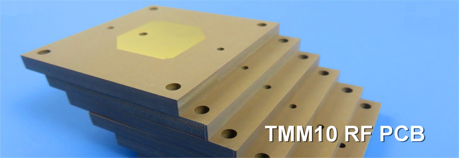
High-Frequency 2-Layer PCB with TP2000 Material: Specifications, Performance & Applications
2026-04-21
If you’ve ever worked on high-frequency RF or microwave projects, you know how much the right PCB material and manufacturing specs can make or break your design. Signal loss, instability in harsh environments, or poor compatibility with assembly processes—these are all pain points we’ve faced. Today, I’m sharing a specialized 2-layer rigid PCB that’s been a game-changer for my team’s high-frequency projects: it’s built around TP2000, a unique thermoplastic material engineered to solve those exact headaches. Let’s walk through its specs, why TP2000 stands out, and where it works best—no overly technical jargon, just practical insights.
1. PCB Construction: Precision Engineering for High-Performance Demands
What makes this PCB stand out isn’t just its material—it’s the attention to detail in every construction choice, balanced to keep performance high while keeping manufacturing straightforward. Here’s a breakdown of the key specs you’ll care about (with quick context on why they matter):
Board Dimensions: 85mm x 85mm (single piece), with a tight ±0.15mm tolerance. This consistency is a lifesaver for assembly—no more struggling to fit PCBs into enclosures or align components.
Trace & Space: 6 mils (trace) / 7 mils (space). For high-frequency paths, this balance keeps signal integrity intact without making the design too complex to manufacture.
Hole Specifications: 0.35mm minimum hole size, no blind vias. Blind vias add complexity (and cost), so skipping them keeps manufacturing simple while still ensuring reliable connectivity for through-hole parts.
Finished Board Thickness: 6.1mm. This isn’t your standard thin PCB—it’s robust enough to handle harsh environments, which is a must for aerospace, defense, or automotive radar projects.
Copper Weight & Plating: 1oz (35μm) outer copper, 20μm via plating. Low resistance here means less signal loss and more reliable current transfer—critical for high-frequency performance.
Surface & Layer Treatments: Bare copper (no solder mask or silkscreen on either side). This is intentional—extra coatings can add parasitic capacitance and signal loss, so bare copper keeps high-frequency performance sharp.
Quality Assurance: 100% electrical testing before shipment. Nothing is more frustrating than receiving a batch of PCBs with short circuits—this step ensures you’re getting reliable boards right out of the box.
2. PCB Stackup: Simplified 2-Layer Design with TP2000 Core
One of the best things about this PCB is its simple 2-layer stackup—no overcomplicating with extra layers, which keeps costs down and performance focused. Here’s how it’s built (top to bottom, with quick context):
Copper Layer 1 (35μm / 1oz): This is your top signal layer—where all those high-frequency signals travel, so the 1oz copper keeps loss low.
TP2000 Core (6mm): The star of the show—this is the dielectric layer that makes high-frequency performance possible (we’ll dive deeper into TP2000 next).
Copper Layer 2 (35μm / 1oz): The bottom layer, usually used as a ground or secondary signal layer—critical for balanced signal return paths (no more signal crosstalk!).
This stackup is all about intentional simplicity. By cutting out unnecessary layers, we keep the PCB compact while letting the TP2000 core do its job—delivering the signal integrity you need for high-frequency RF and microwave work.
3. Manufacturing & Quality Standards
When you’re ordering PCBs for critical projects, consistency and compatibility matter. This PCB checks both boxes with industry-standard manufacturing and quality specs:
Artwork Format: Gerber RS-274-X. If you’ve ordered PCBs before, you know this is the standard—every major manufacturer supports it, so you won’t have compatibility issues with your CAM files.
Quality Standard: IPC-Class 2. This is the sweet spot for most commercial high-frequency projects—it’s strict enough to ensure reliability, but not overkill (like IPC-Class 3, which is for military/aerospace-grade projects).
Availability: Worldwide. No matter where your team or manufacturing partner is, you can get this PCB—consistent quality, no matter the location.
4. TP2000 Material: The Secret to High-Frequency Excellence
Let’s get to the heart of what makes this PCB special: TP2000. If you’re tired of FR-4 struggling with high-frequency signal loss (we’ve all been there), TP2000 is a game-changer. It’s a unique high-frequency thermoplastic material, made from ceramic and polyphenylene oxide (PPO) resin—no glass fiber reinforcement, which is key for its performance. Unlike FR-4, it’s engineered specifically for RF and microwave applications, so it solves the signal loss and instability issues we often face with traditional materials.
What does that mean for your project? TP2000 has an ultra-high dielectric constant, ultra-low signal loss, and excellent thermal stability—all while being easy to machine and compatible with standard PCB manufacturing. For high-frequency designs (think GHz range), these properties are non-negotiable—they keep your signals clean, reduce distortion, and ensure reliability even in tough conditions.
Key TP2000 Features (The Ones That Matter for Your Projects)
Dielectric Constant (DK): 20 at 5GHz. Higher DK means better signal propagation—perfect for compact high-frequency designs where space is limited.
Dissipation Factor (Df): 0.002 at 5GHz. Ultra-low signal loss—this is where TP2000 crushes FR-4. Less loss means your signals stay strong, even at high frequencies.
Thermal Coefficient of DK (TCDK): -55 ppm/°C. Stable dielectric performance, even when temperatures change—critical for outdoor, automotive, or aerospace projects.
Coefficient of Thermal Expansion (CTE): X=35 ppm/°C, Y=35 ppm/°C, Z=40 ppm/°C. Minimal warpage, so your PCB stays aligned during assembly and in harsh environments.
Operating Temperature Range: -100°C to +150°C. It handles extreme cold (think space applications) and heat (automotive underhood) without breaking a sweat.
Bonus Perks: High mechanical strength, radiation resistance (great for satellite projects), easy to drill/cut, compatible with standard assembly, and UL 94-V0 flame rating (extra safety for critical designs).
5. Typical Applications: Where This PCB Shines
Now that we’ve covered the specs and TP2000’s benefits, let’s talk real-world use cases. This PCB isn’t a one-size-fits-all—it’s built for projects where high signal integrity and reliability are non-negotiable. Here’s where it shines:
High-frequency RF and microwave circuits: Where low signal loss is make-or-break (think communication systems).
Antenna systems (including phased array antennas): TP2000’s high DK and low Df improve signal propagation—perfect for precision antennas.
Radar systems (automotive, aerospace, defense): Handles extreme temperatures and harsh conditions—no performance drop when it matters most.
Satellite communication equipment: Radiation resistance and wide temperature range make it ideal for orbital applications.
High-power RF amplifiers: Low dissipation factor means less energy loss—more efficient, more reliable.
Test and measurement instruments: Precise signal integrity ensures accurate readings—no more faulty measurements.
Aerospace and defense electronics: Meets strict reliability standards—critical for life-or-death applications.
6. Why Choose This TP2000 PCB?
If you’re still on the fence, let’s break down why this TP2000 PCB is worth considering for your next high-frequency project. For starters, TP2000 solves the biggest pain point with FR-4: signal loss at high frequencies. Add in the simple 2-layer design (lower cost, less complexity) and strict manufacturing specs (consistent, reliable), and you’ve got a PCB that’s both practical and high-performance.
We’ve used this PCB in everything from satellite communication modules to automotive radar systems, and it’s consistently delivered. With worldwide availability, IPC-Class 2 quality, and 100% electrical testing, it takes the guesswork out of sourcing high-frequency PCBs. If you’re tired of compromising on signal integrity or dealing with unreliable boards, this one’s worth a look.
View More
Computing power soars, PCB leads the gains. Can this highprosperity be sustained
2026-04-15
Data shows that on April 13, the PCB sector saw a net inflow of 2.38 billion yuan in main capital. Against the backdrop of intensifying competition in AI computing power, the PCB sector has recently strengthened noticeably. At this current juncture, the market is more concerned about whether this rally is merely a phased recovery driven by sentiment, or the starting point of a new round of growth following the continued strengthening of industrial logic. Please see the latest institutional analysis.
Regarding the latest catalysts, the current PCB market trend is driven by both supply and demand factors.
On one hand, demand for computing power has not cooled; instead, stronger validation signals have emerged recently.
As of the evening of April 12, concerning NVIDIA's (NVDA) next-generation Rubin platform, the latest supply chain information clearly indicates that the company has abandoned the previously expected pure M9 solution, opting instead for a "hybrid pressing" technical approach using both M8 and M8 materials. This involves using different grades of CCL material layered within the same PCB board based on signal transmission requirements. This adjustment in technical roadmap is not a downgrade but a pragmatic choice to balance performance and yield. It will accelerate the commercial demand for M9 core materials (such as Q-fabric), while creating a smoother path for incremental growth for CCL manufacturers that have a complete product matrix from M8 to M9.
On April 10, TSMC (TSM) reported a 35.1% year-on-year revenue increase for the first quarter of 2026, exceeding market expectations. Research reports generally attribute this to persistently strong AI demand. Simultaneously, Anthropic's annualized revenue is rapidly increasing, and it has signed next-generation TPU computing power agreements with Google (GOOG) and Broadcom (AVGO). Broadcom (AVGO) disclosed that it will provide 1GW of computing power for Anthropic in 2026, with projections exceeding 3.5GW in 2027. Multiple AI-PCB companies are experiencing strong orders, operating at full capacity with sold-out production, and are actively expanding. The industry is in a state of "rising prices and volumes."
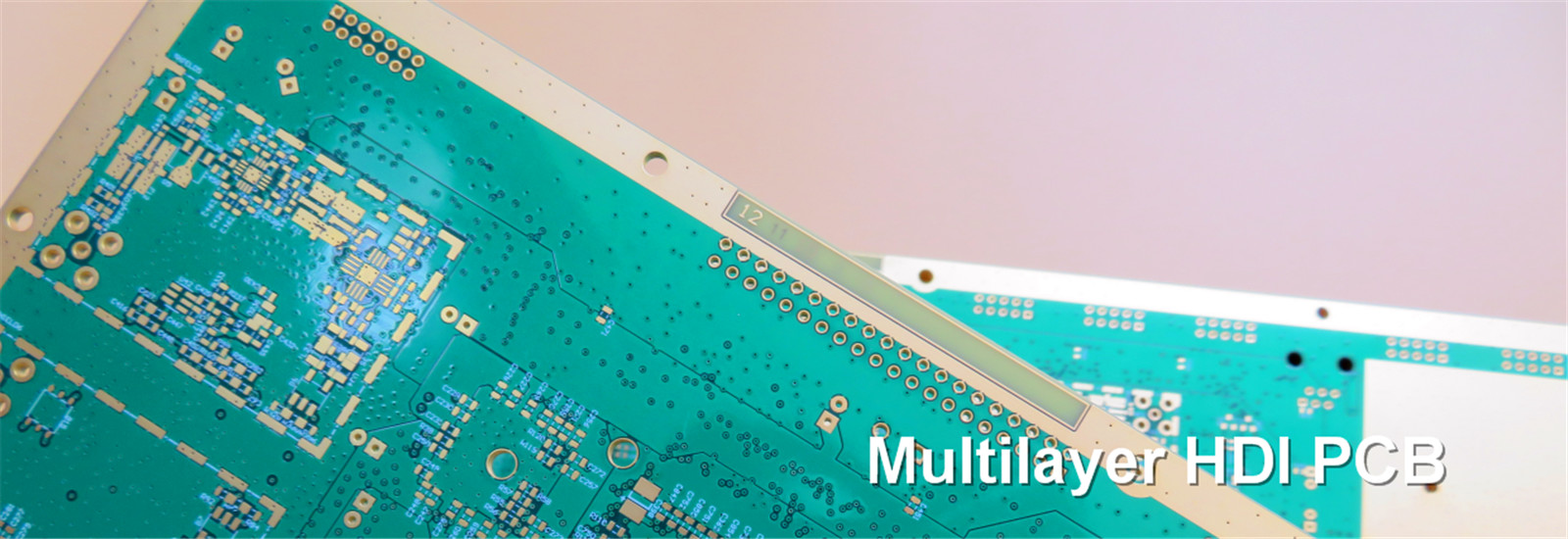
Institutions generally believe that the market is no longer just trading on "increased demand" but on "upward value chain movement." With the continuous upgrading of AI servers, PCBs are consistently evolving from traditional multi-layer boards to high multi-layer and high-end HDI boards. In the long term, computing power will accelerate towards ASIC (Application-Specific Integrated Circuit) adoption. The value of PCBs for ASIC server motherboards per unit is significantly higher than that for same-generation GPU servers. Coupled with upgrades in high-end materials and processes like M7 and M8, the value increase for PCBs is not a short-term spike but a systemic elevation brought about by changes in hardware architecture. This means the core of this round of sector performance is not just increased shipment volumes, but also the simultaneous upward revision of per-unit value, technical barriers, and profit elasticity.
On the other hand, the tight supply-demand balance on the supply side and material upgrades are becoming another important logic supporting the sustainability of the market trend.
The latest supply chain tracking shows that the overall PCB industry maintained a high level of prosperity in the first quarter, with prices for mid-to-low-end raw materials and copper-clad laminates (CCL) rising successively. Furthermore, recent geopolitical conflicts have further pushed up raw material prices. While this increases short-term volatility, it also reinforces expectations of price increases for high-prosperity segments from another perspective. Currently, M7-grade and above materials are widely used in scenarios like AI servers and 5G base stations. Materials for the next-generation Rubin platform, M9, are expected to see volume growth, while testing clues for M10 have also emerged.
Institutions suggest that this implies the market is not simply trading an "electronics rebound," but rather an industrial upgrade characterized by the accelerated positioning of high-end materials, high-end processes, and high-end capacity. The slow pace of supply-side expansion, sluggish overseas CCL capacity expansion, and accelerated entry of domestic leaders suggest that the prosperity sustainability of the PCB sector may be stronger than the market previously expected.
Synthesizing views from multiple institutions, investors looking to seize investment opportunities in the current PCB sector can focus on the following two main themes:
First, leading PCB manufacturers with mass production capabilities for high-end HDI and high multi-layer boards, such as Victory Giant Technology (HK2476), Wus Printed Circuit (002463), Kinwong Electronic (603228), and Aoshikang Technology (002913). These companies are more directly benefiting from the surge in demand for AI servers and high-speed communications, as well as material upgrades.
Second, leading domestic suppliers of high-speed CCL. From an industry chain layout perspective, domestic leading companies such as Sheng Yi Technology (600183), Nanya New Material Technology (688519), and Huazheng New Material (603186) offer products covering M8 to M9/M10 grades. They have already secured their technological positions in advance and can fully meet the diverse material needs arising from hybrid pressing solutions.
--------------------------------------
Source: Securities Times
Disclaimer: We respect originality and also value sharing; the copyright of text and images belongs to the original authors. The purpose of reprinting is to share more information, which does not represent the position of this account. If your rights are infringed, please contact us immediately for deletion. Thank you.
View More
Resin Price Hikes Begin, Leading to Sustained Inflation in Upstream PCB Materials
2026-04-15
On April 3, Kingboard issued a notice stating that due to a sharp rise in chemical product prices and tight supply, the cost of copper-clad laminates (CCL) has increased dramatically. Effective immediately, Kingboard will uniformly increase the prices of its CCL sheets and PP (prepreg) by 10%.
We believe this price increase is primarily driven by rising resin costs resulting from geopolitical tensions in the Middle East. Affected by the situation in the Middle East, prices of chemical products such as epoxy resin, natural gas, and TBBA have surged amid tight supply. According to the Epoxy Review, taking East China as a benchmark, the ex-factory price (net of water) of liquid E-51 epoxy resin on April 3 closed at RMB 18,300–19,500 per ton, an increase of approximately 40% since the outbreak of the conflict.
Further price increases for FR-4 CCL are likely, with high industry concentration giving CCL manufacturers the upper hand. Expectations of tight supply for the three main raw materials—copper foil, resin, and fiberglass fabric—continue to strengthen. Copper prices are expected to remain high due to tight supply-demand balance. AI-grade specialty fabrics are taking up production capacity, and under supply constraints, the upward momentum for standard fabrics may persist. Earlier, fabric prices saw concentrated increases in early January, early February, early March, and late March.
The price increase of electronic-grade PPO is driven by rising costs, but more fundamentally by a supply-demand gap.
On the supply-demand front, total supply of electronic-grade PPO by the end of 2026 is expected to be around 6,000 tons. However, with the increase in shipments of M8-M9 grade CCL, industry demand is expected to rise to 7,000–8,000 tons, leading to a widening supply-demand gap by the end of the year. On the cost side, the average price of phenol, PPO's core raw material, rose 34.55% in March compared to February. PPO manufacturers have strong intentions to pass on cost increases.
Resin could be one of the decisive factors in pushing CCL to its limits.
On one hand, as copper foil and fiberglass fabric—two major raw materials—gradually approach their performance limits, resin, which relies on formulation rather than being a standalone component, becomes increasingly important for formulation optimization. On the other hand, the core know-how in CCL manufacturing lies in adjusting the resin formulation (including resin, silica powder, additives, etc.). The upgrade to M9-M10 requires CCL manufacturers to guide upstream suppliers on resin formulations. Therefore, as M10 upgrades and iterations become a clear future direction, the resin system will undoubtedly play a key role.
Focus on domestic computing power and breakthroughs in China-made CCL, highlighting resin leader Shengquan Group.
On the demand side, sales of domestic chips like the 950 may exceed market expectations, accelerating earnings releases in the second half of 2026 for PCBs, CCLs, and upstream materials in the domestic computing power supply chain. On the supply side, domestic CCL manufacturers such as Shengyi are not only breaking into the NV supply chain but also benefiting from the growth of domestic computing power. Shengquan Group, as a resin supplier to domestic CCL makers and the domestic computing power chain, stands to benefit significantly, with earnings potentially accelerating from the second half of 2026.
Resin price hikes begin, leading to sustained inflation in upstream PCB materials.
This round of price increases is essentially a visible transmission of cost pressures from upstream raw materials. We reiterate our positive outlook on core material segments (resin, fiberglass fabric, copper foil, additives). This round of price increases validates the strength of their fundamentals.
Supply constraints are the core driver: The main reason for the price hikes is "tight supply." Upstream chemical raw materials currently face structural constraints, including global geopolitical instability, stricter environmental inspections, the phase-out of old capacity, and restrictions on new capacity additions. The chemical industry's upcycle is just beginning. With inelastic supply, the sustainability of high prices may exceed market expectations.
Industry position and pricing power are increasing amid industry restructuring: In the chain of "basic chemical raw materials → electronic-grade materials (resin/additives) → CCL → PCB," the electronic-grade material segment features high technical barriers and long certification cycles. Upstream companies are currently enjoying the dual benefits of rigid demand (AI servers, AI hardware, etc.) and limited supply, significantly enhancing their bargaining power vis-à-vis midstream players.
CCL leader's price hike is a key validation signal: Kingboard, an industry leader with superior cost-control capabilities, sending a price hike notice sends two signals:
Upward price pressure from upstream validates the reality and intensity of cost-push inflation.
It provides a pricing anchor for the entire CCL industry, opening room for other manufacturers to raise prices.
----------------------------------------
Source: Research Highlights
Disclaimer: We respect originality and also value sharing; the copyright of text and images belongs to the original authors. The purpose of reprinting is to share more information, which does not represent the position of this account. If your rights are infringed, please contact us immediately for deletion. Thank you.
View More