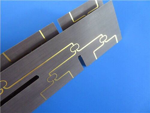
This PCB employs Wangling's F4BM217 laminate as the base material and strictly complies with IPC-Class-2 quality criteria, a double-sided rigid configuration specifically engineered to satisfy the rigorous performance requirements of microwave, radio frequency (RF), and other high-frequency electronic systems.
PCB Specifications
The PCB features a double-sided construction with precise specifications to ensure optimal functionality. Key construction parameters are as follows:
| Construction Parameter |
Details |
| Base Material |
Wangling F4BM217 |
| Layer Count |
2-layer rigid structure. |
| Board Dimensions |
120mm x 89mm per piece, with a tolerance of ±0.15mm. |
| Trace/Space |
6 mils / 7 mils |
| Minimum Hole Size |
0.3mm |
| Blind Vias |
No |
| Finished Board Thickness |
0.17mm |
| Finished Copper Weight |
1oz (equivalent to 1.4 mils) on outer layers |
| Via Plating Thickness |
20 μm, enhancing via conductivity and durability. |
| Surface Finish |
Immersion Gold, providing excellent corrosion resistance, solderability, and long-term reliability. |
| Silkscreen |
No silkscreen on both top and bottom layers |
| Solder Mask |
No solder mask on both top and bottom layers |
| Quality Control |
100% electrical testing performed prior to shipment |
Stack-up Configuration
| Layer |
Specification |
Function |
| Copper Layer 1 |
35 μm (1oz) thickness |
Top signal layer |
|
F4BM217 Core
|
0.1mm thickness |
Dielectric base with excellent electrical properties |
| Copper Layer 2 |
35 μm (1oz) thickness |
Bottom signal layer |

F4BM217 Material Introduction
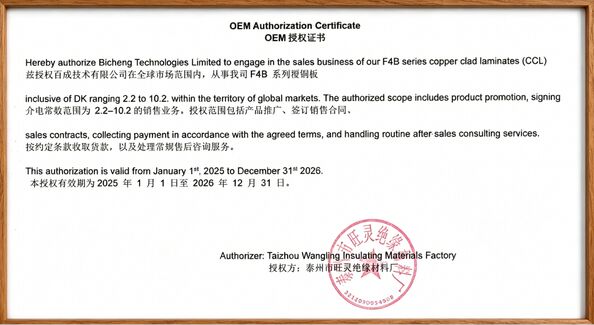
Wangling's F4BM217 laminates are advanced dielectric materials crafted through scientific formulation and strict pressing processes. They consist of a combination of fiberglass cloth, polytetrafluoroethylene (PTFE) resin, and PTFE film, delivering enhanced electrical performance compared to F4B220 laminates—primarily characterized by lower dielectric loss, higher insulation resistance, and improved stability. This material is a viable alternative to similar foreign products, offering cost-effectiveness without compromising quality.
F4BM217 and F4BME217 share the same dielectric layer but differ in copper foil combinations:
- F4BM217 is paired with ED copper foil, making it ideal for applications without PIM (Passive Intermodulation) requirements.
- F4BME217 uses reverse-treated foil (RTF) copper foil, providing excellent PIM performance, more precise line width control, and lower conductor loss.
By adjusting the ratio of PTFE to fiberglass cloth, both F4BM217 and F4BME217 achieve precise control of the dielectric constant. A higher fiberglass proportion results in a higher dielectric constant, accompanied by better dimensional stability, a lower coefficient of thermal expansion (CTE), improved temperature drift performance, and a slight increase in dielectric loss—allowing customization based on application needs.
F4BM217 Material Features
F4BM217 laminates exhibit outstanding electrical and mechanical properties, including:
| Property |
Specification |
Description |
| Dielectric Constant (Dk) |
2.17±0.04 at 10GHz |
Ensures stable signal transmission in high-frequency applications. |
| Dissipation Factor (Df) |
0.001 at 10GHz |
Minimizes signal attenuation and energy loss. |
| Coefficient of Thermal Expansion (CTE) |
X-axis 25 ppm/°C, Y-axis 34 ppm/°C, Z-axis 240 ppm/°C (-55°C to 288°C) |
Enables reliable performance under extreme temperature fluctuations. |
| Thermal Coefficient of Dk |
-150 ppm/°C (-55°C to 150°C) |
Ensures stable dielectric properties across temperature variations. |
| Moisture Absorption |
≤0.08% |
Reduces the impact of humidity on electrical performance and reliability. |
| Flammability Rating |
UL-94 V0 |
Meets strict fire safety standards for electronic components. |
Typical Applications
Leveraging its exceptional high-frequency performance and stability, this PCB is well-suited for the following applications:
-Microwave, RF, and radar systems
-Phase shifters
-Passive components
-Power dividers, couplers, and combiners
-Feed networks
-Phased array antennas
-Satellite communications systems
-Base station antennas
Quality & Supply Information
Quality Standard: Complies with IPC-Class-2, ensuring reliable performance for commercial electronic products.
Artwork Format: Gerber RS-274-X, the industry-standard format for PCB manufacturing, ensuring compatibility with most production processes.
Availability: Supplied worldwide, supporting global project requirements.

 Your message must be between 20-3,000 characters!
 English