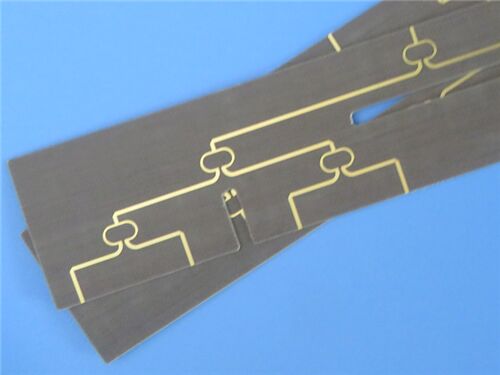
This is a 2-layer rigid PCB fabricated from Rogers RT/duroid 5870, a high-frequency glass microfiber-reinforced PTFE composite. Optimized for precision stripline/microstrip designs, it delivers uniform dielectric performance and ultra-low loss, ideal for Ku-band and millimeter-wave applications. This PCB features a finished thickness of 0.3mm, 1 oz (1.4 mils) copper cladding on both outer layers, and an Electroless Nickel Immersion Gold (ENIG) surface finish.
PCB Specifications
| Specification Item |
Technical Specification |
| Base Substrate Material |
Rogers RT/duroid 5870 |
| Layer Configuration |
2 Layers (Double-Sided Rigid) |
| Board Dimensions |
85mm x 36mm (per unit), with a dimensional tolerance of ±0.15mm |
| Minimum Trace Width/Space |
5/6 mils |
| Minimum Drill Hole Size |
0.4mm |
| Blind Vias Configuration |
Not Incorporated |
| Finished Board Thickness |
0.3mm |
| Finished Copper Weight (Outer Layers) |
1 oz (1.4 mils) |
| Via Plating Thickness |
20 μm |
| Surface Finish |
Electroless Nickel Immersion Gold (ENIG) |
| Top Silkscreen |
Not Incorporated |
| Bottom Silkscreen |
Not Incorporated |
| Top Solder Mask |
Not Incorporated |
| Bottom Solder Mask |
Not Incorporated |
| Electrical Testing Requirements |
100% electrical functionality testing is conducted prior to shipment to ensure operational integrity |
PCB Stack-Up Configuration
This 2-layer rigid PCB adopts a symmetric stack-up structure, with detailed layer specifications provided below (ordered from top to bottom):
| Layer Designation |
Technical Specification |
| Copper Layer 1 (Top) |
35 μm |
| RT/duroid 5870 Core Substrate |
0.254 mm (10mil) |
| Copper Layer 2 (Bottom) |
35 μm |

Artwork Format and Quality Compliance
The Gerber RS-274-X format is designated as the artwork standard for this PCB, a globally accepted benchmark within the printed circuit board manufacturing industry. This standard ensures seamless compatibility with professional PCB design software and automated fabrication equipment, enabling the precise translation of digital circuit layouts into physical PCB assemblies. Additionally, this PCB complies with the IPC-Class-2 quality standard, which establishes rigorous requirements for performance, reliability, and manufacturing consistency—validating its suitability for deployment in commercial and industrial electronic applications.
Global Availability
This high-performance PCB is available for global shipment. It accommodates both prototyping needs and large-volume production orders, ensuring universal accessibility and timely delivery to customers across the world.
RT/duroid 5870 Substrate Introduction
Rogers RT/duroid 5870 high-frequency laminates are PTFE composite materials reinforced with glass microfibers, specifically developed for high-precision stripline and microstrip circuit applications. The randomly oriented microfibers within RT/duroid 5870 contribute to exceptional dielectric constant uniformity, which remains consistent across individual panels and over a broad frequency spectrum. Its low dissipation factor extends the material’s applicability to Ku-band and higher frequency ranges. Furthermore, RT/duroid 5870 laminates are easily cut, sheared, and machined to precise shapes, and they demonstrate resistance to all solvents and reagents—whether hot or cold—that are commonly utilized in printed circuit etching or edge/hole plating processes.
Core Benefits of RT/duroid 5870
- Uniform electrical properties across a wide frequency range, ensuring consistent and reliable performance
- Facilitates streamlined fabrication, as it can be easily cut, sheared, and machined to precise dimensions
- Resistant to solvents and reagents used in etching or edge/hole plating processes, minimizing manufacturing defects
- Low moisture absorption makes it well-suited for deployment in high-moisture environments
- A well-established material with a proven track record of reliability in high-frequency applications
- Offers the lowest electrical loss among reinforced PTFE materials, optimizing signal integrity in high-frequency systems
Typical Applications
- Commercial Airline Broadband Antennas
- Microstrip and Stripline Circuits
- Millimeter Wave Applications
- Radar Systems
- Guidance Systems
- Point-to-Point Digital Radio Antennas
RT/duroid 5870 High Frequency Laminates
RT/duroid 5870 glass microfiber reinforced PTFE composites are engineered for demanding stripline and microstrip circuit applications. The random orientation of the microfibers provides exceptional uniformity in dielectric constant.
The dielectric constant of RT/duroid 5870 laminates remains consistent from panel to panel and stays stable across a wide frequency range. Its low dissipation factor makes RT/duroid 5870 laminates highly effective for applications up to Ku-band and beyond.
Fabrication and Handling
RT/duroid 5870 laminates are easy to cut, shear, and machine into desired shapes. They are resistant to all common solvents and reagents—both hot and cold—used in etching printed circuits or plating edges and holes.
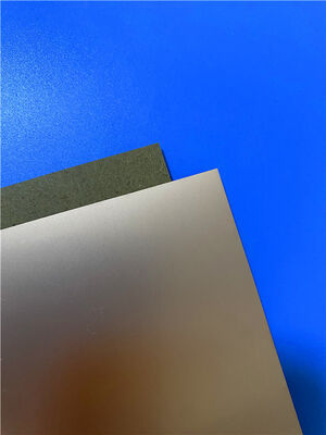
Cladding Options
These laminates are typically supplied with electrodeposited copper cladding (½ to 2 oz/ft², or 8 to 70 μm) or reverse-treated EDC copper on both sides. For more demanding electrical applications, RT/duroid 5870 composites can also be clad with rolled copper foil. Cladding with aluminum, copper, or brass plates is also available upon request.
Ordering Information
When ordering RT/duroid 5870 laminates, it is essential to specify:
Dielectric thickness and tolerance
Copper foil type (rolled, electrodeposited, or reverse treated)
Required copper foil weight
| RT/duroid 5870 Typical Value |
| Property |
RT/duroid 5870 |
Direction |
Units |
Condition |
Test Method |
| Dielectric Constant,εProcess |
2.33
2.33±0.02 spec. |
Z |
N/A |
C24/23/50
C24/23/50 |
1 MHz IPC-TM-650 2.5.5.3
10 GHz IPC-TM 2.5.5.5 |
| Dielectric Constant,εDesign |
2.33 |
Z |
N/A |
8GHz to 40 GHz |
Differential Phase Length Method |
| Dissipation Factor,tanδ |
0.0005
0.0012 |
Z |
N/A |
C24/23/50
C24/23/50 |
1 MHz IPC-TM-650 2.5.5.3
10 GHz IPC-TM 2.5.5.5 |
| Thermal Coefficient of ε |
-115 |
Z |
ppm/℃ |
-50℃to 150℃ |
IPC-TM-650 2.5.5.5 |
| Volume Resistivity |
2 x 10⁷ |
Z |
Mohm cm |
C/96/35/90 |
ASTM D 257 |
| Surface Resistivity |
2 x 10⁷ |
Z |
Mohm |
C/96/35/90 |
ASTM D 257 |
| Specific Heat |
0.96(0.23) |
N/A |
j/g/k
(cal/g/c) |
N/A |
Calculated |
| Tensile Modulus |
Test at 23℃ |
Test at 100℃ |
N/A |
MPa(kpsi) |
A |
ASTM D 638 |
| 1300(189) |
490(71) |
X |
| 1280(185) |
430(63) |
Y |
| Ultimate Stress |
50(7.3) |
34(4.8) |
X |
| 42(6.1) |
34(4.8) |
Y |
| Ultimate Strain |
9.8 |
8.7 |
X |
% |
| 9.8 |
8.6 |
Y |
| Compressive Modulus |
1210(176) |
680(99) |
X |
MPa(kpsi) |
A |
ASTM D 695 |
| 1360(198) |
860(125) |
Y |
| 803(120) |
520(76) |
Z |
| Ultimate Stress |
30(4.4) |
23(3.4) |
X |
| 37(5.3) |
25(3.7) |
Y |
| 54(7.8) |
37(5.3) |
Z |
| Ultimate Strain |
4 |
4.3 |
X |
% |
| 3.3 |
3.3 |
Y |
| 8.7 |
8.5 |
Z |
| Moisture Absorption |
0.02 |
N/A |
% |
0.62"(1.6mm) D48/50 |
ASTM D 570 |
| Thermal Conductivity |
0.22 |
Z |
W/m/k |
80℃ |
ASTM C 518 |
| Coefficient of Thermal Expansion |
22
28
173 |
X
Y
Z |
ppm/℃ |
0-100℃ |
IPC-TM-650 2.4.41 |
| Td |
500 |
N/A |
℃ TGA |
N/A |
ASTM D 3850 |
| Density |
2.2 |
N/A |
gm/cm3 |
N/A |
ASTM D 792 |
| Copper Peel |
27.2(4.8) |
N/A |
Pli(N/mm) |
1oz(35mm)EDC foil
after solder float |
IPC-TM-650 2.4.8 |
| Flammability |
V-0 |
N/A |
N/A |
N/A |
UL 94 |
| Lead-free Process Compatible |
Yes |
N/A |
N/A |
N/A |
N/A |

 Your message must be between 20-3,000 characters!
 English