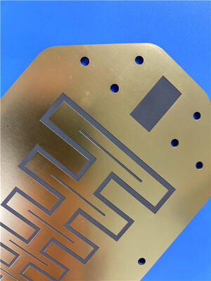
This is a 2-layer rigid PCB fabricated with high-performance RF-grade material RF-30A, which is engineered with an advanced resin system and optimized glass fabric reinforcement. The PCB integrates RF-30A's exceptional high-frequency signal transmission, low dielectric loss and outstanding environmental stability, compliant with industrial standards. It features a 0.6mm finished thickness, 1 oz copper weight for outer layers, and Electroless Nickel Immersion Gold (ENIG) surface finish, ensuring reliable performance for high-speed, high-frequency RF and electronic applications.
PCB Details
| Item |
Specification |
| Base material |
RF-30A |
| Layer count |
2 layers |
| Board dimensions |
85.6mm x 99.8mm (per piece) |
| Minimum Trace/Space |
4/6 mils |
| Minimum Hole Size |
0.25mm |
| Blind vias |
None |
| Finished board thickness |
0.6mm |
| Finished Cu weight (outer layers) |
1 oz (1.4 mils) |
| Via plating thickness |
20 μm |
| Surface finish |
Electroless Nickel Immersion Gold (ENIG) |
| Top Silkscreen |
White |
| Bottom Silkscreen |
No |
| Top Solder Mask |
Green |
| Bottom Solder Mask |
No |
| Electrical test |
100% electrical test conducted prior to shipment |
PCB Stack-up
This is a 2-layer rigid PCB with the following stack-up structure (from top to bottom):
| Layer Type |
Specification |
| Copper_layer_1 |
35 μm |
| RF-30A |
20mil (0.508mm) |
| Copper_layer_2 |
35 μm |

Artwork and Quality Standard
Gerber RS-274-X is the specified artwork format for this PCB, which is universally recognized as the industry standard for PCB fabrication. This format ensures compatibility with most professional manufacturing equipment and design software, allowing for accurate conversion of circuit design data into physical PCBs. Furthermore, the PCB meets the requirements of the IPC-Class-2 standard, which establishes strict performance and reliability guidelines for electronic components, ensuring the product is suitable for commercial and industrial operational needs.
Availability
This high-performance PCB is available worldwide, enabling shipment to every country across the globe without geographical restrictions, catering to both prototyping and large-volume production orders.
Introduction of RF-30A
RF-30A is a high-performance RF-grade laminate material engineered with advanced resin system and optimized glass fabric reinforcement, delivering exceptional high-frequency signal transmission performance, low dielectric loss and outstanding environmental stability. It is specifically designed for high-speed, high-frequency RF applications and can fully comply with 260℃ lead-free assembly processes, ensuring reliable performance in harsh operating conditions.
Typical Applications
- RF/Microwave Communication Devices
- 5G/6G Base Stations & Antennas
- Radar Systems
- Satellite Communication Equipment
- RF Modules & Transceivers
- Aerospace & Defense Electronics
- High-Frequency Test Instruments
- Automotive RF Components (V2X, Radar)
RF-30A – Stable Performance Laminate
RF-30A is an organic-ceramic laminate within AGC's family of RF substrates, constructed with woven glass reinforcement. This product draws on AGC's expertise in both ceramic filler and PTFE coating technologies. RF-30A is an ideal choice for low-cost, high-volume commercial microwave and RF applications.
RF-30A delivers electrical and mechanical stability that exceeds typical design requirements. The combination of a low-loss dielectric substrate and low-profile copper foil provides stable electrical performance, improved PIMD levels, and lower insertion loss across a broad frequency range. Enhanced mechanical stability—characterized by lower CTE values, better dimensional stability, and greater rigidity—ensures that RF components are less affected by external factors.
The excellent peel strength of RF-30A for ½ oz and 1 oz RT copper is critical for applications requiring rework or repeated reflow soldering processes. An ultra-low moisture absorption rate, combined with a stable loss tangent, helps minimize phase shift across varying temperature and humidity conditions. Reduced dimensional movement also contributes to stable phase and impedance properties over a wide frequency range.
RF-30A has been optimized with ceramic fillers to achieve a low Z-axis CTE, improving PTH reliability and simplifying the fabrication of multilayer circuits. These properties also support more stable PIMD performance.
Benefits
- Excellent PIM performance in PCBs (measured below -160 dBc*)
- Improved plated through-hole (PTH) quality
- Stable mechanical properties
- Reliable performance at high frequencies
- Stable under high-temperature conditions
- Low moisture absorption
- High peel strength
- Exceptional price-to-performance ratio
| Properties |
Conditions |
Typical Value |
Unit |
Test Method |
| Dielectric Constant |
@ 1.9 GHz |
2.97 ± 0.05 |
|
IPC-TM 650 2.5.5.5.1 mod |
| Dissipation Factor |
@ 1.9 GHz |
0.0013 |
|
IPC-TM 650 2.5.5.5.1 mod |
| @ 10 GHz |
0.0020 |
|
IPC-TM 650 2.5.5.5.1 mod |
| Volume Resistivity |
|
3.0 x 10⁹ |
Mohm·cm |
IPC-650 2.5.17.1 |
| Surface Resistivity |
|
2.0 x 10⁸ |
Mohms |
IPC-650 2.5.17.1 |
| Thermal Conductivity |
|
0.42 |
W/M*K |
IPC-650 2.4.50 |
|
CTE (50-150°C)
|
X |
8 |
ppm/°C
|
IPC-650 2.4.41
|
| Y |
11 |
| Z |
60 |
| Specific Heat |
|
0.95 |
J/gK |
IPC-650 2.4.50 |
| Density |
Specific Gravity |
2.16 |
g/cm3 |
IPC-TM-650 2.3.5 |
| Flexural Strength |
MD |
126.5 (18,000) |
N/mm2 (psi) |
IPC-650 2.4.18.3 |
| CD |
119.5 (17,000) |
N/mm2 (psi) |
IPC-650 2.4.19 |
| Tensile Strength |
MD |
133.6 (19,000) |
N/mm2 (psi) |
IPC-TM-650 2.4.18.3 |
| CD |
105.5 (15,000) |
N/mm2 (psi) |
IPC-650 2.4.19 |
|
Dimensional Stability
|
MD |
0.049
0.025
|
% (30 mil)
% (60 mil)
|
IPC-650 2.4.39 (After Etch)
|
| CD |
0.041
0.026
|
% (30 mil)
% (60 mil)
|
| MD |
0.049
0.019
|
% (30 mil)
% (60 mil)
|
IPC-650 2.4.39 (After Stress)
|
| CD |
0.031
0.011
|
% (30 mil)
% (60 mil)
|
| Typical Thicknesses |
| Inches |
mm |
| 0.020 |
0.51 |
| 0.030 |
0.76 |
| 0.040 |
1.02 |
| 0.060 |
1.52 |
| Available Sheet Sizes |
| Inches |
mm |
| 12 x 18 |
305 x 457 |
| 16 x 18 |
406 x 457 |
| 18 x 24 |
457 x 610 |
| 36 x 48 |
914 x 1,220 |

 Your message must be between 20-3,000 characters!
 English