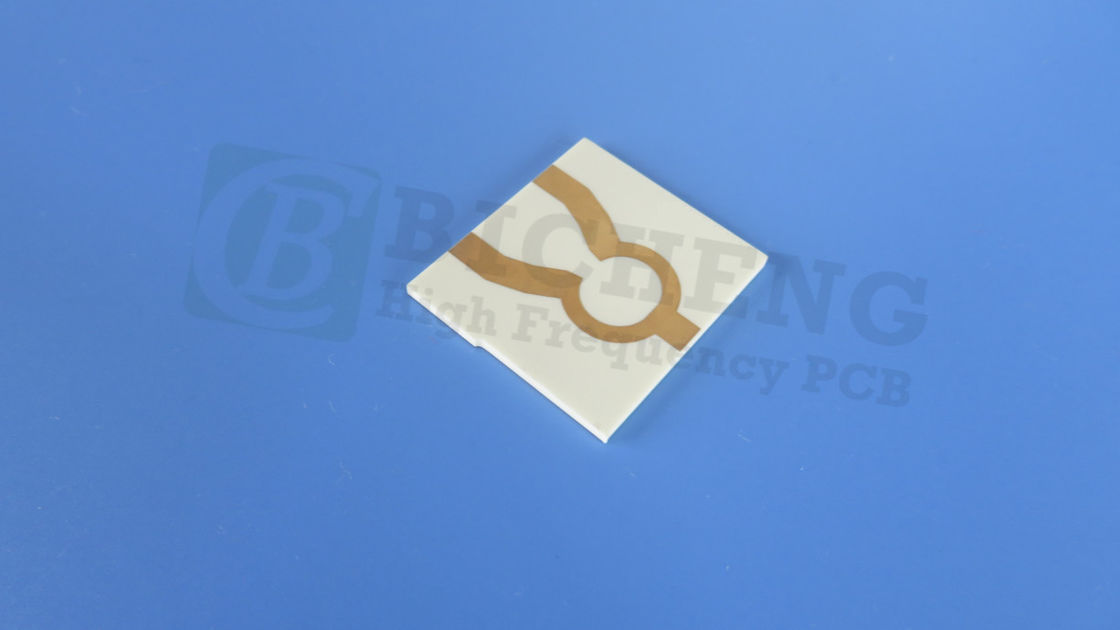
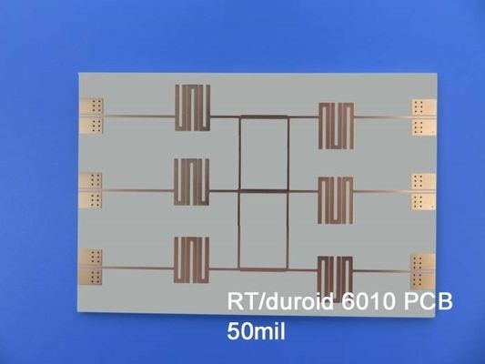
Introducing the RT/duroid 6010.2LM PCB, a high-performance solution specifically engineered for electronic and microwave circuit applications. Crafted from advanced ceramic-PTFE composites, this laminate offers a high dielectric constant, making it ideal for applications requiring significant circuit size reduction. Designed for low-loss performance, it excels in X-band operations and below, ensuring reliable and repeatable circuit performance.
What is RT/duroid 6010.2LM?
RT/duroid 6010.2LM is a sophisticated laminate material composed of ceramic-PTFE composites. These materials are engineered to meet the stringent requirements of high-frequency applications, where traditional materials may fall short. The high dielectric constant and low loss characteristics make this laminate particularly suitable for applications operating at X-band frequencies and below.
Key Characteristics
1. High Dielectric Constant (Dk):
The RT/duroid 6010.2LM boasts a Dk of 10.2 ± 0.25 at 10GHz. This high dielectric constant enables significant circuit size reduction, allowing for more compact designs without sacrificing performance.
2. Low Loss:
With a dissipation factor of 0.0023 at 10GHz, this material minimizes signal loss, making it ideal for high-frequency applications. This property is crucial for maintaining signal integrity in microwave communications.
3. Thermal Stability:
The laminate has a decomposition temperature (Td) of 500 °C, indicating its ability to withstand high temperatures during processing. This thermal stability, coupled with a low coefficient of thermal expansion (CTE) of 24 ppm/°C in the x and y directions and 47 ppm/°C in the z direction, ensures reliable performance in varying environmental conditions.
4. Moisture Resistance:
With a moisture absorption rate of only 0.01%, the RT/duroid 6010.2LM effectively mitigates the risks associated with moisture-related electrical losses, enhancing the reliability of the circuits.
5. Flammability Rating:
The material meets the V-0 flammability rating per UL94, ensuring safety in high-risk applications.
PCB Construction
| Property |
RT/duroid 6010 |
Direction |
Units |
Condition |
Test Method |
| Dielectric Constant,εProcess |
10.2±0.25 |
Z |
|
10 GHz/23℃ |
IPC-TM-650 2.5.5.5 Clamped stripline |
| Dielectric Constant,εDesign |
10.7 |
Z |
|
8GHz to 40 GHz |
Differential Phase Length Method |
| Dissipation Factor,tanδ |
0.0023 |
Z |
|
10 GHz/A |
IPC-TM-650 2.5.5.5 |
| Thermal Coefficient of ε |
-425 |
Z |
ppm/℃ |
-50℃-170℃ |
IPC-TM-650 2.5.5.5 |
| Volume Resistivity |
5 x 10⁵ |
|
Mohm.cm |
A |
IPC 2.5.17.1 |
| Surface Resistivity |
5 x 10⁶ |
|
Mohm |
A |
IPC 2.5.17.1 |
| Tensile Properties |
ASTM D638 (0.1/min. strain rate) |
| Young's Modulus |
931(135) 559(81) |
X Y |
MPa(kpsi) |
A |
| Ultimate Stress |
17(2.4) 13(1.9) |
X Y |
MPa(kpsi) |
A |
| Ultimate Strain |
9 to 15 7 to 14 |
X Y |
% |
A |
| Compressive Properties |
|
ASTM D695 (0.05/min. strain rate) |
| Young's Modulus |
2144 (311) |
Z |
MPa(kpsi) |
A |
| Ultimate Stress |
47(6.9) |
Z |
MPa(kpsi) |
A |
| Ultimate Strain |
25 |
Z |
% |
|
| Flexural Modulus |
4364 (633) 3751 (544) |
X |
MPa(kpsi) |
A |
ASTM D790 |
| Ultimate Stress |
36 (5.2) 32 (4.4) |
X Y |
MPa(kpsi) |
A |
| Deformation under load |
0.26 1.3 |
Z Z |
% |
24hr/50℃/7MPa 24hr/150℃/7MPa |
ASTM D261 |
| Moisture Absorption |
0.01 |
|
% |
D48/50℃ 0.050"(1.27mm) thick |
IPC-TM-650 2.6.2.1 |
| Thermal Conductivity |
0.86 |
|
W/m/k |
80℃ |
ASTM C518 |
| Coefficient of Thermal Expansion |
24
24
47 |
X
Y
Z |
ppm/℃ |
23℃/50% RH |
IPC-TM-650 2.4.41 |
| Td |
500 |
|
℃ TGA |
|
ASTM D3850 |
| Density |
3.1 |
|
g/cm3 |
|
ASTM D792 |
| Specific Heat |
1.00(0.239) |
|
j/g/k
(BTU/ib/OF) |
|
Calculated |
| Copper Peel |
12.3 (2.1) |
|
pli (N/mm) |
after solder float |
IPC-TM-650 2.4.8 |
| Flammability |
V-0 |
|
|
|
UL 94 |
| Lead-free Process Compatible |
Yes |
|
|
|
|
Stackup Design
This PCB is constructed with a 2-layer rigid design, which includes:
Copper Layer 1: 35 μm
Core Material: Rogers RT/duroid 6010.2LM, measuring 0.254 mm (10 mil)
Copper Layer 2: 35 μm
Dimensions and Specifications
Board Dimensions: 46 mm x 54.3 mm, with a tolerance of ± 0.15 mm.
Minimum Trace/Space: 4/4 mils, allowing for precise routing of signals.
Minimum Hole Size: 0.5 mm, accommodating various component types.
Finished Board Thickness: 0.3 mm, optimizing the board’s profile for compact applications.
Finished Copper Weight: 1 oz (1.4 mils) for outer layers, balancing conductivity and thermal dissipation.
Surface Finish and Quality Assurance
Surface Finish: Immersion Silver, providing excellent solderability and protection against oxidation.
Silkscreen and Solder Mask: The top silkscreen is white, while the top solder mask is green, facilitating easy identification of components and connections. The bottom side has no silkscreen or solder mask, reducing cost and complexity.
Electrical Testing: Each PCB undergoes 100% electrical testing prior to shipment, ensuring that every unit meets stringent quality standards.

Benefits of Using RT/duroid 6010.2LM PCB
1.Circuit Size Reduction:
The high dielectric constant allows for smaller circuit designs, enabling more compact electronic devices.
2. Enhanced Performance:
Low loss characteristics ensure that signals remain strong, reducing the need for additional amplifiers or signal conditioning.
3. Reliability in Multilayer Boards:
The low Z-axis expansion supports the integrity of plated through holes, vital for multilayer applications.
4. Resilience to Environmental Factors:
Low moisture absorption and high thermal stability provide robust performance in diverse operating conditions.
5. Consistency in Manufacturing:
Tight control over dielectric constant and thickness ensures repeatable performance across production runs.
| PCB Material: |
Ceramic-PTFE composite |
| Designator: |
RT/duroid 6010LM |
| Dielectric constant: |
10.2 ±0.25 (process); 10.7 (design) |
| Layer count: |
1 Layer, 2 Layer |
| Copper weight: |
0.5oz (17 µm), 1oz (35µm), 2oz (70µm) |
| Dielectric thickness: |
10mil (0.254mm), 25mil (0.635mm), 50mil (1.27mm), 75mil (1.90mm) |
| PCB size: |
≤400mm X 500mm |
| Solder mask: |
Green, Black, Blue, Yellow, Red etc. |
| Surface finish: |
Bare copper, HASL, ENIG, Immersion tin, Immersion Silver, OSP. |
Typical Applications
The versatility of the RT/duroid 6010.2LM PCB allows it to be employed in various high-tech applications, including:
Patch Antennas: Used in wireless communication devices for signal transmission.
Satellite Communications Systems: Essential for reliable data transmission in space applications.
Power Amplifiers: Critical components in RF applications, providing necessary amplification for signals.
Aircraft Collision Avoidance Systems: Vital for enhancing safety in aviation through effective signal processing.
Ground Radar Warning Systems: Employed in military and defense applications for threat detection.
Conclusion
The RT/duroid 6010.2LM PCB stands as a testament to the advancements in PCB technology, addressing the growing demands for high-frequency performance, reliability, and miniaturization in electronic design. Its unique combination of features and benefits make it an ideal choice for engineers and manufacturers looking to innovate in the fields of telecommunications, aerospace, and defense. By choosing the RT/duroid 6010.2LM PCB, you not only invest in superior technology but also ensure the success of your electronic applications in an increasingly competitive market.


 Your message must be between 20-3,000 characters!
 English