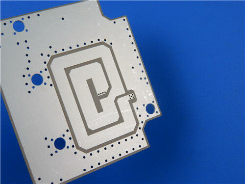
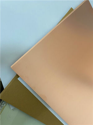
This 2-layer rigid TF960 PCB serves as a high-stability high-frequency solution tailored for high-precision radio frequency and wireless signal processing devices. Constructed with premium TF960 thermoset ceramic-filled modified PTFE dielectric material, this PCB delivers steady dielectric performance, ultra-low signal loss and superior thermal stability, offering better structural dependability and processing compatibility than conventional high-frequency substrates. It features a 0.7mm final board thickness and 1 oz outer copper layer, paired with immersion silver surface finishing to ensure stable solderability and consistent electrical conductivity during long-duration high-frequency operation. Built with 5/8 mil fine-line routing capability and 0.25mm micro-hole precision, the board adopts a non-blind via design with customized single-sided coating, including white top silkscreen and blue top solder mask, while the bottom copper layer remains exposed.
PCB Specification
| Specification Item |
Details |
| Base Material |
TF960 thermoset modified PTFE ceramic-filled high-frequency laminate |
| Layer Count |
2 layers (rigid PCB) |
| Finished Board Thickness |
0.7mm |
| Board Dimensions |
102mm x 86mm (1PCS), tolerance +/-0.15mm |
| Finished Copper Weight |
1 oz (1.4 mils) outer layers |
| Via Plating Thickness |
20 μm |
| Minimum Trace/Space |
5/8 mils |
| Minimum Hole Size |
0.25mm |
| Blind Vias |
None |
| Surface Finish |
Immersion Silver |
| Silkscreen |
White top silkscreen, no bottom silkscreen |
| Solder Mask |
Blue top solder mask, no bottom solder mask |
| Quality Standard |
IPC-Class-2 |
| Testing Process |
100% electrical test prior to shipment |
PCB Stack-up Structure
Featuring a symmetrical dual-layer rigid layout with a high-stability TF960 dielectric core, this stackup structure achieves balanced mechanical flatness and uniform electrical parameters. It is fully compatible with standard FR4 drilling, plating and lamination procedures, ensuring reliable manufacturing consistency and steady signal transmission for high-frequency circuit designs.
| Stack-up Layer |
Specification Details |
| Copper Layer 1 |
35 μm copper foil |
| TF960 Substrate Core |
0.635mm (25mil) thermoset high-frequency dielectric core |
| Copper Layer 2 |
35 μm copper foil |

PCB Statistic
This TF960 high-frequency PCB adopts optimized component placement and rational via distribution, catering to compact assembly requirements and sustaining stable electrical performance for precision RF functional modules.
| Statistical Item |
Quantity |
| Total Components |
49 |
| Total Pads |
57 |
| Thru Hole Pads |
32 |
| Top SMT Pads |
25 |
| Bottom SMT Pads |
0 |
| Vias Quantity |
43 |
| Nets Quantity |
2 |
TF960 High-Frequency Substrate Introduction
TF960 is a premium thermoset high-frequency laminate composed of modified PTFE resin, micron-sized ceramic fillers and glass fiber reinforcement. Compared with traditional high-frequency dielectrics, this upgraded material provides lower dielectric dissipation, tighter dielectric constant tolerance and enhanced structural stability. It supports standard FR4 manufacturing workflows and 260℃ lead-free reflow soldering, featuring outstanding thermal endurance and minimal moisture absorption. Developed for high-reliability RF circuit systems, TF960 effectively reduces insertion loss and maintains complete signal integrity under prolonged high-frequency operating conditions.
TF960 Core Characteristics
TF960 combines precisely calibrated dielectric characteristics and robust mechanical properties, delivering stable and repeatable high-frequency performance for commercial and industrial RF scenarios:
| Performance Parameter |
Performance Description |
| Dielectric Constant (Dk) |
9.6 ± 0.19 at 10GHz, supporting precise and consistent impedance tuning for high-frequency circuit design |
| Dissipation Factor (Df) |
0.0012 at 10GHz, realizing ultra-low signal dissipation to preserve optimal signal integrity |
| CTE Coefficient |
X=50 ppm/℃, Y=50 ppm/℃, Z=65 ppm/℃, delivering superior dimensional stability during thermal cycling and assembly processes |
| Moisture Absorption |
≤0.05%, minimizing humidity-induced parameter deviation and improving long-term operational reliability |
| Flammability Rating |
UL 94-V0 flame retardant grade, conforming to international electronic safety regulations |
Typical Applications
Benefiting from accurate dielectric consistency, ultra-low high-frequency dissipation and excellent thermal and environmental resistance, TF960 PCBs are widely utilized in high-end communication equipment, industrial precision testing and high-reliability radar systems:
- RF and microwave transceiving modules
- 5G/6G massive MIMO antenna arrays
- Automotive ADAS and aerospace radar systems
- Satellite communication payload devices
- High-power RF amplifier units
- High-precision test and measurement instruments, including vector network analyzers
Quality & Service Guarantee
All TF960 high-frequency circuit boards are fabricated in strict accordance with IPC-Class-2 industrial quality criteria. Adopting standard Gerber RS-274-X design files, each board achieves precise dimensional precision and stable electrical repeatability for batch manufacturing. Every finished product undergoes comprehensive electrical inspection before shipment to eliminate functional defects and ensure consistent batch performance. Supported by global logistics networks and professional technical assistance, these high-reliability high-frequency PCB solutions deliver dependable support for high-end communication, aerospace, automotive and precision measurement projects across the globe.


 Your message must be between 20-3,000 characters!
 English