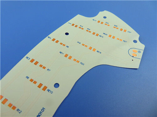
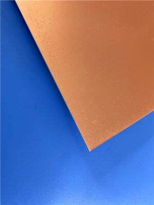
This 2-layer rigid TFA1020 high-frequency PCB is a premium aerospace-grade circuit solution engineered for rigorous microwave and radio frequency application scenarios. Adopting innovative glass-free PTFE nano-ceramic composite dielectric substrate, this circuit board abandons traditional fiberglass-reinforced structures, completely eliminating electromagnetic wave propagation interference caused by glass fibers. It delivers outstanding frequency stability and ultra-low signal loss, offering superior overall performance compared with conventional high-frequency PCB substrates. Featuring an ultra-slim 0.25mm finished thickness and 1oz outer copper cladding, the board adopts pure gold plating surface treatment to deliver excellent electrical conductivity, durable oxidation resistance and long-term operational stability for high-precision aerospace, radar and satellite devices. It supports 4/6 mil fine-line trace and space routing, alongside 0.35mm minimum hole fabrication, with a non-blind via design. The board is processed as full bare copper without any top/bottom solder mask or silkscreen printing.
PCB Specification
| Specification Item |
Details |
| Base Material |
TFA1020 glass-free PTFE nano-ceramic composite high-frequency laminate |
| Layer Configuration |
2-layer rigid PCB structure |
| Finished Board Thickness |
0.25mm |
| Board Dimension |
67.4mm × 89mm (1PCS), dimensional tolerance: ±0.15mm |
| Outer Copper Thickness |
1 oz (1.4 mils) finished copper weight for outer layers |
| Via Plating Depth |
20 μm plating thickness |
| Minimum Trace/Space |
4/6 mils |
| Minimum Drilling Hole Size |
0.35mm |
| Blind Vias Design |
Not adopted |
| Surface Finishing |
Pure Gold Plating |
| Silkscreen Printing |
No printing on top and bottom sides |
| Solder Mask Coating |
No coating on top and bottom sides |
| Pre-Shipment Test |
100% full electrical inspection |
PCB Stack-up Structure
This symmetrical dual-layer rigid stackup adopts an ultra-thin TFA1020 nano-ceramic PTFE dielectric core. The unique glass-free structural design greatly reduces X/Y/Z three-dimensional anisotropy, delivering thermal expansion properties highly matched to copper foil. It effectively eliminates electromagnetic signal distortion caused by traditional fiberglass weaving, maintaining uniform electrical performance and outstanding dimensional stability for high-precision aerospace high-frequency circuit applications.
| Stack-up Layer |
Parameter Details |
| Top Copper Layer |
35 μm thick copper foil |
| TFA1020 Dielectric Core |
0.127mm (5mil) high-performance glass-free composite substrate |
| Bottom Copper Layer |
35 μm thick copper foil |

PCB Statistic
This TFA1020 aerospace-grade high-frequency PCB features streamlined component layout and reasonable via distribution. The optimized structural layout adapts to miniaturized precision assembly requirements, sustaining stable and accurate signal transmission for sophisticated RF functional modules.
| Statistical Item |
Quantity |
| Mounted Components |
24 |
| Total Pad Count |
30 |
| Through-Hole Pads |
18 |
| Top SMT Pads |
12 |
| Bottom SMT Pads |
0 |
| Via Quantity |
11 |
| Net Circuit Quantity |
2 |
TFA Series High-Frequency Substrate Overview
TFA series substrates are advanced PTFE ceramic composite dielectric materials tailored for aerospace high-reliability scenarios. Different from conventional high-frequency laminates that adopt glass fiber cloth resin impregnation technology, TFA series utilizes innovative nano-ceramic and PTFE resin integrated molding, paired with exclusive customized lamination processes. Completely free of glass fiber components, the material eliminates the fiberglass effect during electromagnetic transmission, achieving superior frequency stability and industry-leading low dielectric loss. It features minimized multi-directional anisotropy, copper-matched low thermal expansion coefficient and stable dielectric temperature characteristics, fully capable of replacing imported equivalent high-end substrates. The series supports four optional dielectric constants including 2.94, 3.0, 6.15 and 10.2, corresponding to TFA294, TFA300, TFA615 and TFA1020 models to meet diverse high-frequency circuit design demands.
TFA1020 Core Material Advantages
TFA1020 integrates ultra-low signal attenuation, outstanding temperature adaptability and efficient heat dissipation performance. Its stable electrical and mechanical properties ensure consistent and reliable operation of high-frequency circuits under extreme and harsh working environments:
| Performance Parameter |
Performance Advantage |
| Dielectric Constant (Dk) |
10.2 at 10GHz, enabling precise impedance matching and stable parameter output for compact high-frequency aerospace circuit designs |
| Dissipation Factor (Df) |
0.0015 at 10GHz and 0.0017 at 20GHz, effectively reducing broadband signal loss and retaining complete signal integrity |
| Temperature Coefficient of Dielectric Constant (TCDK) |
-340 ppm/°C within -55°C to 150°C, maintaining steady dielectric performance amid drastic temperature fluctuations |
| CTE Parameter |
X=16 ppm/°C, Y=16 ppm/°C, Z=30 ppm/°C (-55°C to 288°C), delivering copper-synced dimensional stability during assembly and thermal cycling |
| Thermal Conductivity |
0.88 W/mk, accelerating heat dissipation and improving long-term operational stability of high-power RF devices |
| Moisture Absorption Rate |
0.015% ultra-low water absorption, preventing parameter deviation caused by humid environments and enhancing environmental adaptability |
| Flame Retardant Grade |
UL 94-V0, complying with strict aerospace and industrial electronic safety specifications |
Typical Application Scenarios
Benefiting from glass-free ultra-stable dielectric performance, minimal high-frequency loss, excellent temperature resistance and aerospace-grade reliability, TFA1020 PCBs are widely applied in high-end aviation, aerospace, precision radar and satellite communication fields:
- Aerospace craft, space exploration equipment and airborne cabin electronic systems
- Microwave signal processing devices and high-precision phase-sensitive antenna equipment
- Early warning radar systems and airborne radar facilities
- Phased array antenna systems and RF beamforming network modules
- Satellite communication and navigation positioning equipment
- High-performance RF power amplifier modules
Quality Assurance & Global Service
All TFA1020 aerospace-grade high-frequency PCBs are fabricated in strict accordance with IPC-Class-2 industrial quality standards. Adopting standard Gerber RS-274-X design files, each circuit board features precise dimensional accuracy and excellent electrical repeatability, supporting high-standard batch production. Every finished product undergoes full-coverage electrical performance testing before shipment to rule out functional defects and ensure uniform batch quality. Supported by global logistics networks and professional technical after-sales services, these high-reliability glass-free low-loss PCB solutions provide stable and dependable support for aerospace, defense, satellite communication and precision radar projects worldwide.


 Your message must be between 20-3,000 characters!
 English