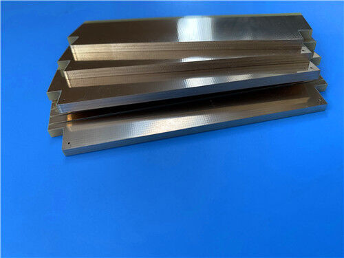
This PCB utilizes I-Tera MT40 laminates and RO4450F prepreg (PP), ensuring superior signal integrity for high-speed digital and RF/microwave applications. It features 2u" Immersion Gold (ENIG) finish, double-sided green solder mask with white silkscreen, and is engineered to meet stringent performance requirements of high-reliability systems through precise dimensional control, strict impedance management, and rigorous quality protocols.
PCB Details
| Construction Parameter |
Specification |
| Base material |
I-Tera MT40 + RO4450F Prepreg |
| Layer count |
6 layers |
| Board dimensions |
99mm × 99mm per piece |
| Finished board thickness |
1.501mm (after lamination) |
| Finished Cu weight |
Outer layers: 2oz; Inner layers: 1oz finished copper |
| Surface finish |
Immersion Gold (ENIG), 2u" |
| Solder Mask & Silkscreen |
Double-sided: Green solder mask and white silkscreen |
| Impedance Control |
TOP layer: 5mil trace, single end impedance control, 50 ohm |
| Via Configuration |
Blind vias; 0.3mm vias with resin plugging and electroplating capping for leveling |
| Special Feature |
Edge plating (metal edge wrapping) |
| Quality test |
100% Electrical test conducted prior to shipment |
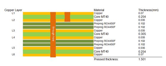
PCB Stack-up
| Layer Type |
Specification (From Top to Bottom) |
| Copper Layer (Outer) |
Copper_layer_1 (TOP): 2oz (70μm) |
| Dielectric Layer |
I-Tera MT40: 0.254mm |
| Copper Layer (Inner) |
Copper_layer_2: 1oz (35μm) |
| Prepreg Layer (PP) - RO4450F (Layer 1) |
RO4450F Prepreg - 0.102mm |
| Prepreg Layer (PP) - RO4450F (Layer 2) |
RO4450F Prepreg - 0.102mm |
| Copper Layer (Inner) |
Copper_layer_3: 1oz (35μm) |
| Core Layer |
I-Tera MT40: 0.305mm |
| Copper Layer (Inner) |
Copper_layer_4: 1oz (35μm) |
| Prepreg Layer (PP) - RO4450F (Layer 1) |
RO4450F Prepreg - 0.102mm |
| Prepreg Layer (PP) - RO4450F (Layer 2) |
RO4450F Prepreg - 0.102mm |
| Copper Layer (Inner) |
Copper_layer_5: 1oz (35μm) |
| Dielectric Layer |
I-Tera MT40: 0.254mm |
| Copper Layer (Outer) |
Copper_layer_6 (Bottom): 2oz (70μm) |

Artwork Type
To ensure accurate and efficient PCB manufacturing, the artwork supplied for this PCB is in Gerber RS-274-X format, which is the industry-standard file format for PCB fabrication.
Quality Standard
This PCB is manufactured and inspected in strict compliance with the IPC-Class-2 standard, a widely adopted industry standard for printed circuit boards. IPC-Class-2 specifies requirements for general electronic products, ensuring reliable performance in typical applications.
Availability
This PCB is offered globally, with a stable supply capability to accommodate diverse order requirements—ranging from small-batch prototypes to large-scale mass production—backed by efficient logistics solutions to ensure timely global delivery.
Introduction to I-Tera MT40 Material
I-Tera MT40 is a high-performance dielectric material specifically engineered for today’s high-speed digital and RF/microwave printed circuit designs. It features a stable dielectric constant (Dk) across a wide temperature range (-55°C to +125°C) and up to W-band frequencies, combined with a low dissipation factor (Df) of 0.0031, making it a cost-effective alternative to PTFE and other commercial microwave and high-speed digital laminate materials.
I-Tera MT40 laminate materials are available in both laminate and prepreg forms, in typical thicknesses and standard panel sizes, providing a complete material solution for high-speed digital multilayer, hybrid, RF/microwave, multilayer and double-sided printed circuit designs. Unlike PTFE-based laminate materials, I-Tera MT40 does not require any special through-hole treatments, simplifying manufacturing processes and reducing production costs. It is UL 94 V-0 rated, ensuring high flame retardancy and suitability for a wide range of electronic applications.
The thermal performance of I-Tera MT40 is exceptional, with a glass transition temperature (Tg) of 215°C (DSC), 230°C (DMA) and 210°C (TMA), and a decomposition temperature (Td) of 360°C at 5% weight loss. This ensures the material maintains structural stability and performance integrity through high-temperature processing and operational cycles, making it ideal for high-reliability applications.
Features of I-Tera MT40 Material
| Material Property |
Typical Value |
Units |
Test Method |
| Glass Transition Temperature (Tg) by DSC |
215 |
°C |
IPC-TM-650 2.4.25C |
| Glass Transition Temperature (Tg) by DMA |
230 |
°C |
IPC-TM-650 2.4.24.4 |
| Glass Transition Temperature (Tg) by TMA |
210 |
°C |
IPC-TM-650 2.4.24C |
| Decomposition Temperature (Td) @ 5% weight loss |
360 |
°C |
IPC-TM-650 2.4.24.6 |
| Time to Delaminate (T260, Copper removed) |
>60 |
Minutes |
IPC-TM-650 2.4.24.1 |
| Z-Axis CTE (Pre-Tg) |
55 |
ppm/°C |
IPC-TM-650 2.4.24C |
| Z-Axis CTE (Post-Tg) |
290 |
ppm/°C |
IPC-TM-650 2.4.24C |
| X/Y-Axis CTE (Pre-Tg) |
12 |
ppm/°C |
IPC-TM-650 2.4.24C |
| Thermal Conductivity |
0.61 |
W/m·K |
ASTM E1952 |
| Dielectric Constant (Dk) @ 2 GHz |
3.45 |
— |
IPC-TM-650 2.5.5.5 |
| Dissipation Factor (Df) @ 2 GHz |
0.0031 |
— |
Bereskin Stripline |
| Moisture Absorption |
0.1 |
% |
IPC-TM-650 2.6.2.1A |
| Flammability |
V-0 |
Rating |
UL 94 |
Typical Applications of I-Tera MT40
-High-speed digital printed circuit designs
-RF/microwave communication systems
-Multilayer and double-sided PCB designs
-Hybrid printed circuit boards
-High-reliability electronic equipment requiring stable electrical and thermal performance
-Cost-sensitive high-frequency applications (alternative to PTFE materials)
What is Single End Impedance Control?
Single end impedance control (also referred to as single-ended impedance control) is a critical PCB design and manufacturing process that ensures the characteristic impedance of a single conductive trace on the PCB remains consistent and matches the specified value (in this case, 50 ohm for the TOP layer 5mil trace). Impedance is the total opposition to the flow of alternating current (AC) in a circuit, combining resistance, capacitance, and inductance.
For high-speed digital and RF/microwave applications, maintaining precise single end impedance is essential for several reasons: it minimizes signal reflection, reduces signal distortion and crosstalk, ensures efficient signal transmission, and prevents signal integrity issues that can degrade the performance of electronic systems. The 5mil trace on the TOP layer of this PCB is controlled to 50 ohm, which is a standard impedance value for many RF and high-speed digital applications, ensuring compatibility with other components and systems.
Single end impedance control is achieved through careful design of trace width, trace thickness, dielectric material thickness, and the distance between the trace and the reference plane. Strict manufacturing control is also required to ensure consistency in material properties and trace dimensions, as any variation can alter the impedance value.
Why Edge Plating (Metal Edge Wrapping) is Required?
Edge plating, also known as metal edge wrapping, is a PCB manufacturing process that involves plating the exposed edges of the PCB with a conductive metal (typically copper, followed by ENIG to match the surface finish). This process is incorporated into the design of this PCB for several key reasons, all of which enhance the performance, reliability, and manufacturability of the board:
Improved Grounding and Shielding: Edge plating provides a continuous conductive path around the perimeter of the PCB, enhancing grounding integrity and reducing electromagnetic interference (EMI). It acts as a Faraday cage, shielding the internal circuits from external EMI and preventing internal signals from radiating outward, which is critical for RF and high-speed digital applications.
Enhanced Mechanical Strength: The metal plating on the PCB edges increases the mechanical robustness of the board, making it more resistant to edge chipping, cracking, and damage during handling, assembly, and operational use. This is particularly important for PCBs used in harsh environments or applications with high mechanical stress.
Improved Thermal Dissipation: Edge plating serves as an additional thermal path, helping to dissipate heat generated by components on the PCB. This improves the thermal management of the board, preventing thermal accumulation and ensuring the stability and longevity of electronic components.
Facilitates Electrical Continuity: Edge plating can provide electrical continuity between multiple layers of the PCB, simplifying the grounding design and ensuring consistent electrical performance across the entire board. It also helps to reduce resistance at the board edges, improving signal integrity.
Enhanced Solderability and Assembly: Edge plating provides a clean, conductive surface that can facilitate soldering of components or connectors mounted near the board edges, improving the reliability of the assembly process.

 Your message must be between 20-3,000 characters!
 English