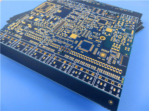
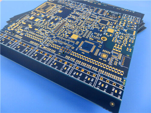
This 4-layer rigid hybrid RF PCB is constructed with F4BM265 high-frequency laminate and S1000-2M series FR-4 dielectric materials, engineered with controlled impedance circuitry and blind via structures. Manufactured complying with IPC-Class-3 reliability criteria, the PCB adopts ENIG surface finish, dual-side blue solder mask with white legend, 25μm hole copper plating, and 35μm finished copper on every conductive layer. It features a total lamination thickness of 4.14mm and board dimension of 245mm×245mm (1pcs), granting stable impedance characteristics, premium dielectric stability and reliable dimensional performance for high-end RF and microwave communication applications.
PCB Specifications
| Parameter Item |
Specification |
| Layer Configuration |
4-layer rigid multilayer PCB |
| Board Dimension |
245mm × 245mm (1 piece) |
| Finished Lamination Thickness |
4.14mm |
| PCB Stack-up Composition |
3mm F4BM265 core + S1000-2MB prepreg + 0.5mm S1000-2M core |
| Finished Copper Thickness |
35μm finished copper for each layer |
| Via Structure |
Blind vias included |
| Via Plating Thickness |
25μm hole copper thickness |
| Impedance Requirement |
Custom controlled impedance design |
| Surface Finishing |
ENIG |
| Solder Mask & Silkscreen |
Blue solder mask + white legend on top & bottom sides |
| Quality Standard |
IPC-Class-3 |

F4BM265 Material Overview
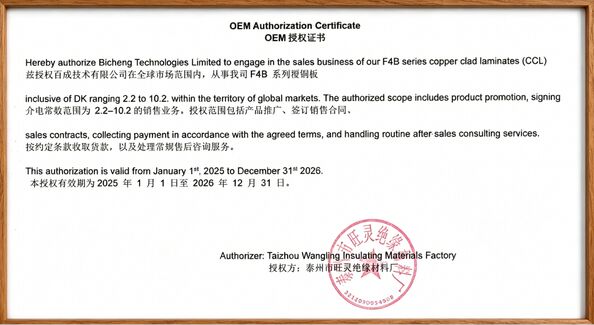
F4BM, F4BME and F4BM265 are glass fabric reinforced PTFE copper clad laminates fabricated via standardized lamination process with compounded glass fabric, PTFE resin and PTFE film. With upgraded electrical properties versus standard F4B substrates, they feature broader tunable Dk range, lower dielectric loss, higher insulation resistance and enhanced operational stability, serving as qualified alternatives to imported peer high-frequency laminates.
F4BM and F4BME share the identical dielectric core but differ in copper foil configuration. F4BM is bonded with ED copper foil for projects with no PIM performance requirements; F4BME adopts reversed RTF copper foil to realize superior PIM performance, precise circuit profiling and reduced conductor loss. Its dielectric constant can be precisely modulated by adjusting the proportion of PTFE resin and glass fabric. Higher glass fiber content contributes to higher Dk, better dimensional stability, lower CTE, optimized temperature drift property, with a minor rise on dielectric loss.
Core Material Characteristics
Tunable Dielectric Constant: Standard Dk ranging from 2.17 to 3.0, custom Dk available on demand
Low RF Dielectric Loss: Optimized compound formula minimizes high-frequency signal attenuation
Superior PIM Performance: F4BME variant with reversed RTF copper foil delivers excellent PIM performance
Optimized Cost Efficiency: Multiple available board sizes to cut overall fabrication cost
Special Environmental Resistance: Outstanding anti-radiation capability and low outgassing property
Mass Production Availability: Commercial-scale supply with stable cost-performance ratio
Typical Application Scenarios
- Microwave & RF circuits, military radar systems
- Phase shifters and microwave passive components
- Power dividers, couplers and signal combiners
- Antenna feed networks and phased array antenna systems
- Satellite communication terminals and base station antennas


 Your message must be between 20-3,000 characters!
 English