Introduction:
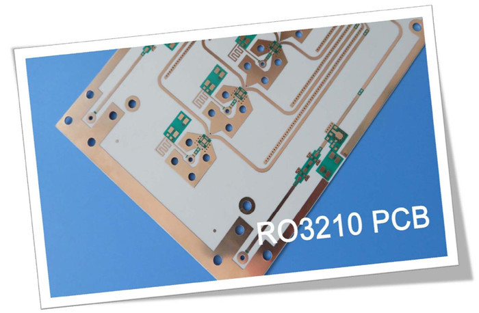
It's delighted to share a new RF PCB which made of RO3210 25mil laminates. The RO3210 high-frequency circuit materials are a game-changer in the world of PCBs. These ceramic-filled laminates, reinforced with woven fiberglass, offer exceptional electrical performance and mechanical stability. Designed with the aim of providing improved mechanical stability, RO3210 laminates combine the surface smoothness of a non-woven PTFE laminate with the rigidity of a woven-glass PTFE laminate. This article dives deep into the features, benefits, construction details, and applications of the newly shipped RO3210-based PCB.
Features:
The RO3210 material boasts an impressive array of features that set it apart from conventional circuit materials. These include:
1. Dielectric constant (Dk) of 10.2 +/- 0.5, ensuring precise signal transmission.
2. Dissipation factor of .0027 at 10GHz, minimizing signal loss.
3. Coefficient of thermal expansion matched to copper, promoting excellent thermal stability.
4. Decomposition Temperature (Td) of 500°C TGA, ensuring high-temperature resilience.
5. Coefficient of Thermal Expansion (CTE) of 13 ppm/°C (x and y axes) and 34 ppm/°C (z axis), providing dimensional stability.
6. Thermal Conductivity of 0.81W/mK, facilitating efficient heat dissipation.
7. Flammability rating of V0 UL 94 standard, ensuring safety and compliance.
| Property |
Typical Value RO3210 |
Direction |
Unit |
Condition |
Test Method |
| Dielectric Constant, r Process |
10.2± 0.50 |
Z |
- |
10 GHz 23°C |
IPC-TM-650 2.5.5.5
Clamped Stripline |
| Dielectric Constant, r Design |
10.8 |
Z |
- |
8 GHz - 40 GHz |
Differential Phase Length Method |
| Dissipation Factor, tan |
0.0027 |
Z |
- |
10 GHz 23°C |
IPC-TM-650 2.5.5.5 |
| Thermal Coefficient of r |
-459 |
Z |
ppm/°C |
10 GHz 0-100°C |
IPC-TM-650 2.5.5.5 |
| Dimensional Stability |
0.8 |
X,Y |
mm/m |
COND A |
ASTM D257 |
| Volume Resistivity |
103 |
|
M•cm |
COND A |
IPC 2.5.17.1 |
| Surface Resistivity |
103 |
|
M |
COND A |
IPC 2.5.17.1 |
| Tensile Modulus |
579
517 |
MD CMD |
kpsi |
23°C |
ASTM D638 |
| Water Absorption |
<0.1 |
- |
% |
D24/23 |
IPC-TM-650 2.6.2.1 |
| Specific Heat |
0.79 |
|
J/g/K |
|
Calculated |
| Thermal Conductivity |
0.81 |
- |
W/m/K |
80°C |
ASTM C518 |
| Coefficient of Thermal Expansion (-55 to 288 °C) |
13
34 |
X,Y, Z |
ppm/°C |
23°C/50% RH |
IPC-TM-650 2.4.41 |
| Td |
500 |
|
°C |
TGA |
ASTM D3850 |
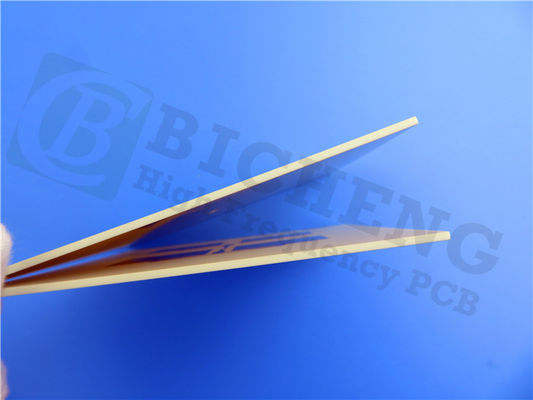
| Color |
Off White |
|
|
|
|
| Density |
3.0 |
|
gm/cm3 |
|
|
| Copper Peel Strength |
11.0 |
|
pli |
1 oz. EDC
After Solder Float |
IPC-TM-2.4.8 |
| Flammability |
V-0 |
|
|
|
UL 94 |
| Lead Free Process Compatible |
YES |
|
|
|
|
Benefits:
The RO3210 substrate offers a range of benefits that enhance its performance and usability:
1. Woven glass reinforcement improves rigidity, making it easier to handle during fabrication.
2. Uniform electrical and mechanical performance makes it ideal for complex multi-layer high-frequency structures.
3. Low in-plane expansion coefficient matched to copper enables use with epoxy multi-layer board hybrid designs and reliable surface-mounted assemblies.
4. Excellent dimensional stability ensures high production yields.
5. Surface smoothness allows for finer line etching tolerances, expanding design possibilities.
PCB Stackup and Construction Details:
This PCB construction details encompass various specifications to ensure optimal performance and adherence to high-quality standards. These include the board dimensions of 20mm x 20mm with a tolerance of +/- 0.15mm, a minimum trace/space requirement of 6/6 mils, and a minimum hole size of 0.25mm. The PCB does not include blind vias and has a finished board thickness of 0.8mm. The outer layers have a finished copper weight of 1oz (1.4 mils), and the via plating thickness measures 20 μm. The surface finish is achieved through immersion tin, while there is no top or bottom silkscreen or solder mask. Additionally, a comprehensive 100% electrical test is conducted prior to shipment, ensuring the PCB's reliability and functionality.
PCB Statistics:
This PCB incorporates three components and a total of six pads, including four thru-hole pads and two top surface mount technology (SMT) pads. Additionally, it features six vias and two nets, enabling efficient electrical connectivity.
Quality Standard and Availability:
This PCB adheres to the IPC-Class-2 quality standard, guaranteeing its superior manufacturing quality and reliability. It is available worldwide, allowing engineers and designers from various regions to access this cutting-edge technology.

Typical Applications:
The versatility of the RO3210 PCB makes it suitable for a wide range of applications, including:
- Automotive collision avoidance systems
- Automotive global positioning satellite antennas
- Wireless telecommunications systems
- Microstrip patch antennas for wireless communications
- Direct broadcast satellites
- Datalink on cable systems
- Remote meter readers
- Power backplanes
- LMDS and wireless broadband
- Base station infrastructure
Conclusion:
The introduction of the RO3210 high-frequency PCB marks a significant milestone in the industry. With its exceptional features, benefits, and adherence to quality standards, this PCB offers unmatched performance and reliability. Whether in automotive, wireless communications, or satellite systems, the RO3210 PCB ensures superior signal integrity, thermal stability, and dimensional accuracy. Its availability worldwide makes it accessible to engineers and designers globally. Embrace the future of PCB technology by incorporating the RO3210 PCB into your next project.

 Your message must be between 20-3,000 characters!
 English