As the demand for high-performance printed circuit boards (PCBs) continues to rise, driven by advancements in technology and increasing complexity of electronic devices, the introduction of the Rogers RO3003 High-Frequency PCB marks a significant milestone in the industry. Designed specifically for commercial microwave and RF applications, this innovative PCB offers exceptional performance characteristics that make it ideal for a variety of advanced uses, including automotive radar, advanced driver assistance systems (ADAS), and 5G wireless infrastructure.
Understanding Rogers RO3003: The Material Advantage
The Rogers RO3003 PCB is constructed from ceramic-filled PTFE composites, which provide numerous advantages over traditional PCB materials. One of the standout features of the RO3003 laminate is its excellent stability of dielectric constant (Dk) across varying temperatures and frequencies. This stability eliminates the step change in Dk that often occurs near room temperature with PTFE glass materials, ensuring reliable performance in critical applications.
Key Features and Specifications
1. Dielectric Constant: The RO3003 PCB has a Dk of 3 ± 0.04 at 10 GHz and 23°C. This low and stable Dk is essential for maintaining signal integrity in high-frequency applications.
2. Dissipation Factor: With a dissipation factor of 0.001 at 10 GHz and 23°C, the RO3003 minimizes signal loss, making it suitable for applications that require high efficiency and low power consumption.
3. Thermal Stability: The RO3003 laminate boasts a thermal degradation temperature (Td) greater than 500°C, ensuring reliable performance even under extreme thermal conditions.
4. Thermal Conductivity: At 0.5 W/mK, the thermal conductivity of the RO3003 allows for effective heat dissipation, which is crucial in high-power applications where overheating can lead to component failure.
5. Absorption: With a moisture absorption rate of only 0.04%, the RO3003 PCB maintains its properties in various environmental conditions, further enhancing its reliability.
6. Coefficient of Thermal Expansion (CTE): The low CTE values (X-axis: 17 ppm/°C, Y-axis: 16 ppm/°C, Z-axis: 25 ppm/°C) ensure that the PCB maintains its dimensional stability across a wide temperature range, which is critical for multi-layer board designs.
| RO3003 Typical Value |
| Property |
RO3003 |
Direction |
Units |
Condition |
Test Method |
| Dielectric Constant,εProcess |
3.0±0.04 |
Z |
|
10 GHz/23℃ |
IPC-TM-650 2.5.5.5 Clamped Stripline |
| Dielectric Constant,εDesign |
3 |
Z |
|
8GHz to 40 GHz |
Differential Phase Length Method |
| Dissipation Factor,tanδ |
0.001 |
Z |
|
10 GHz/23℃ |
IPC-TM-650 2.5.5.5 |
| Thermal Coefficient of ε |
-3 |
Z |
ppm/℃ |
10 GHz -50℃to 150℃ |
IPC-TM-650 2.5.5.5 |
| Dimensional Stability |
0.06
0.07 |
X
Y |
mm/m |
COND A |
IPC-TM-650 2.2.4 |
| Volume Resistivity |
107 |
|
MΩ.cm |
COND A |
IPC 2.5.17.1 |
| Surface Resistivity |
107 |
|
MΩ |
COND A |
IPC 2.5.17.1 |
| Tensile Modulus |
930
823 |
X
Y |
MPa |
23℃ |
ASTM D 638 |
| Moisture Absorption |
0.04 |
|
% |
D48/50 |
IPC-TM-650 2.6.2.1 |
| Specific Heat |
0.9 |
|
j/g/k |
|
Calculated |
| Thermal Conductivity |
0.5 |
|
W/M/K |
50℃ |
ASTM D 5470 |
Coefficient of Thermal Expansion
(-55 to 288℃) |
17
16
25 |
X
Y
Z |
ppm/℃ |
23℃/50% RH |
IPC-TM-650 2.4.4.1 |
| Td |
500 |
|
℃ TGA |
|
ASTM D 3850 |
| Density |
2.1 |
|
gm/cm3 |
23℃ |
ASTM D 792 |
| Copper Peel Stength |
12.7 |
|
Ib/in. |
1oz,EDC After Solder Float |
IPC-TM 2.4.8 |
| Flammability |
V-0 |
|
|
|
UL 94 |
| Lead-free Process Compatible |
Yes |
|
|
|
|
Benefits of the Rogers RO3003 PCB
1. Low Dielectric Loss
The RO3003 PCB’s low dielectric loss allows it to function efficiently in applications operating at frequencies up to 77 GHz. This capability is particularly important for advanced telecommunications technologies and automotive radar systems, where high-frequency signals must be transmitted with minimal degradation.
2. Excellent Mechanical Properties
The mechanical properties of the RO3003 PCB are stable across temperature variations, enabling reliable stripline and multi-layer board constructions. This reliability is essential for high-density designs that require precise electrical characteristics.
3. Uniform Mechanical Properties
The RO3003 offers uniform mechanical properties across a range of dielectric constants, making it suitable for multi-layer board designs that incorporate various materials. This flexibility is particularly beneficial for hybrid designs that combine epoxy glass and other materials.
4. Stable Dielectric Constant
The stable dielectric constant of the RO3003 PCB across temperature and frequency ranges is ideal for various applications, including band pass filters, microstrip patch antennas, and voltage-controlled oscillators. This stability ensures consistent performance in demanding environments.
5. Low In-Plane Expansion Coefficient
The RO3003 PCB’s low in-plane expansion coefficient allows it to match copper, which is crucial for ensuring reliable surface-mounted assemblies. This characteristic minimizes the risk of mechanical stress and failure due to temperature changes.
6. Economical Manufacturing Process
The volume manufacturing process associated with the RO3003 PCB results in economical laminate pricing, making it an attractive option for large-scale production without compromising quality.
PCB Construction and Specifications
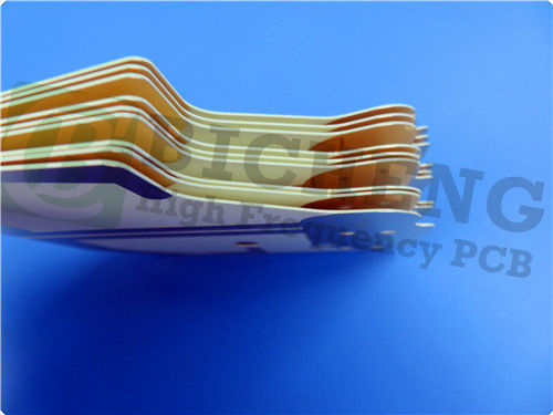
The Rogers RO3003 PCB features a 4-layer rigid stackup, designed for optimal performance:
- Copper Layer 1: 35 μm
- Rogers RO3003: 60 mil (1.524 mm)
- Copper Layer 2: 35 μm
- Prepreg RO4450F: 4 mil (0.101 mm)
- Copper Layer 3: 35 μm
- Rogers RO3003: 20 mil (0.508 mm)
- Copper Layer 4: 35 μm
Important Dimensions and Specifications
- Board Dimensions: 190 mm x 90 mm
- Minimum Trace/Space: 4/4 mils
- Minimum Hole Size: 0.4 mm
- Finished Board Thickness: 2.4 mm
- Finished Copper Weight: 1 oz (1.4 mils)
- Via Plating Thickness: 20 μm
- Surface Finish: Immersion Gold
- Silkscreen Colors: Top - Yellow, Bottom - Green
- Electrical Testing: 100% electrical test prior to shipment

Typical Applications
The Rogers RO3003 PCB is versatile and suitable for a wide range of applications, including:
- Automotive Radar Applications: Supporting advanced driver assistance systems and safety features in vehicles.
- Global Positioning Satellite Antennas: Ensuring reliable signal reception and transmission.
- Cellular Telecommunications Systems: Ideal for power amplifiers and antennas in mobile networks.
- Patch Antennas for Wireless Communications: Facilitating effective data transmission in wireless systems.
- Direct Broadcast Satellites: Ensuring high-quality signal delivery for satellite communications.
- Remote Meter Readers: Supporting efficient data collection in utility industries.
- Power Backplanes: Providing robust support for high-power electronic systems.
Conclusion
The Rogers RO3003 High-Frequency PCB represents a significant advancement in PCB technology, specifically designed to meet the demanding requirements of RF and microwave applications. With its exceptional dielectric stability, low loss characteristics, and robust mechanical properties, the RO3003 PCB is poised to enhance the performance of a wide array of electronic devices.
For more information on the Rogers RO3003 PCB or to discuss your specific project needs, please contact our sales team at sales10@bichengpcb.com. We are committed to providing quality products and exceptional support to help you achieve your project goals.

 Your message must be between 20-3,000 characters!
 English