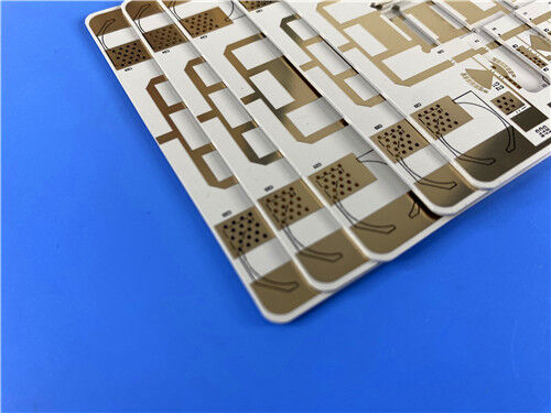
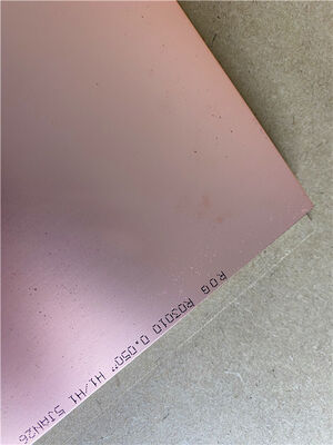
This PCB is a double-sided rigid circuit board made of Rogers RO3010 ceramic-filled PTFE composite material, a high-performance base material known for its excellent dielectric stability and mechanical reliability. This PCB features a board thickness of 1.3mm, 1 oz copper weight on outer layers, and EPIG (nickel free) surface finish, ensuring reliable performance and compatibility for various professional electronic applications that require precision and stability.
PCB Details
| Item |
Specification |
| Base material |
RO3010 |
| Layer count |
Double sided |
| Board dimensions |
89.65mm x 94.3mm (per piece) |
| Minimum Trace/Space |
5/6 mils |
| Minimum Hole Size |
0.25mm |
| Blind vias |
None |
| Finished board thickness |
1.3mm |
| Finished Cu weight (outer layers) |
1 oz (1.4 mils) |
| Via plating thickness |
20 μm |
| Surface finish |
EPIG (nickel free) |
| Top Silkscreen |
Black |
| Bottom Silkscreen |
None |
| Top Solder Mask |
None |
| Bottom Solder Mask |
None |
| Electrical test |
100% electrical test conducted prior to shipment |
PCB Stack-up
This is a 2-layer rigid PCB with the following stack-up structure (from top to bottom):
| Layer Type |
Specification |
| Copper_layer_1 |
35 μm |
| Rogers RO3010 Substrate |
50mil (1.27mm) |
| Copper_layer_2 |
35 μm |

Artwork and Quality Standard
The artwork supplied for this PCB follows the Gerber RS-274-X format, which is the industry-standard file format for PCB manufacturing. Additionally, the PCB adheres to the IPC-Class-2 standard, a widely recognized quality standard that specifies acceptable performance and reliability requirements for electronic components, ensuring the PCB meets the necessary criteria for commercial and industrial applications.
Availability
This PCB is offered for global availability, encompassing all major regions and markets worldwide. Its worldwide accessibility ensures that customers across various countries and industries can obtain the product with consistent reliability and timely delivery, catering to both small-batch prototyping requirements and large-volume production orders.
Introduction to RO3010
Rogers RO3010 high-performance circuit materials are PTFE composites filled with ceramics, featuring a higher dielectric constant while maintaining outstanding stability. These competitively priced products deliver excellent mechanical and electrical reliability. Their inherent stability streamlines the design of broadband components and enables the materials to perform effectively across an extensive frequency range and a wide variety of applications. These characteristics make RO3010 laminates an ideal choice for circuit miniaturization.
Benefits of RO3010 Substrate
The RO3010 substrate demonstrates excellent dimensional stability, with a coefficient of thermal expansion (CTE) precisely matched to copper, ensuring minimal thermal warpage and long-term structural integrity.
The laminate features cost-effective pricing, making it well-suited for high-volume manufacturing processes without compromising performance or quality.
The RO3010 material is manufactured in compliance with ISO 9001 quality management system standards, ensuring consistent product quality and traceability.
The substrate is fully compatible with multi-layer printed circuit board (PCB) designs, providing enhanced flexibility for complex circuit integration.
Typical Applications
- Automotive radar applications
- Global positioning satellite antennas
- Cellular telecommunications systems - power amplifiers and antennas
- Patch antenna for wireless communications
- Direct broadcast satellites
- Datalink on cable systems
- Remote meter readers
- Power backplanes
RO3010 High Frequency Laminates
RO3010 high frequency circuit materials are ceramic-filled PTFE composites designed specifically for commercial microwave and RF applications. This product series combines outstanding electrical and mechanical stability with competitive pricing. RO3000 series laminates are PTFE-based circuit materials filled with ceramics. Their mechanical properties remain consistent regardless of the chosen dielectric constant, enabling designers to develop multilayer boards that incorporate different dielectric constant materials on individual layers—without risk of warpage or reliability issues.
RO3010 laminates can be processed into printed circuit boards using standard PTFE circuit board fabrication techniques.
| Property |
RO3010 |
Direction |
Units |
Condition |
Test Method |
| Dielectric Constant,εProcess |
10.2±0.05 |
Z |
|
10 GHz/23℃ |
IPC-TM-650 2.5.5.5 Clamped Stripline |
| Dielectric Constant,εDesign |
11.2 |
Z |
|
8GHz to 40 GHz |
Differential Phase Length Method |
| Dissipation Factor,tanδ |
0.0022 |
Z |
|
10 GHz/23℃ |
IPC-TM-650 2.5.5.5 |
| Thermal Coefficient of ε |
-395 |
Z |
ppm/℃ |
10 GHz -50℃to 150℃ |
IPC-TM-650 2.5.5.5 |
| Dimensional Stability |
0.35
0.31 |
X
Y |
mm/m |
COND A |
IPC-TM-650 2.2.4 |
| Volume Resistivity |
105 |
|
MΩ.cm |
COND A |
IPC 2.5.17.1 |
| Surface Resistivity |
105 |
|
MΩ |
COND A |
IPC 2.5.17.1 |
| Tensile Modulus |
1902
1934 |
X
Y |
MPa |
23℃ |
ASTM D 638 |
| Moisture Absorption |
0.05 |
|
% |
D48/50 |
IPC-TM-650 2.6.2.1 |
| Specific Heat |
0.8 |
|
j/g/k |
|
Calculated |
| Thermal Conductivity |
0.95 |
|
W/M/K |
50℃ |
ASTM D 5470 |
Coefficient of Thermal Expansion
(-55 to 288℃) |
13
11
16 |
X
Y
Z |
ppm/℃ |
23℃/50% RH |
IPC-TM-650 2.4.4.1 |
| Td |
500 |
|
℃ TGA |
|
ASTM D 3850 |
| Density |
2.8 |
|
gm/cm3 |
23℃ |
ASTM D 792 |
| Copper Peel Stength |
9.4 |
|
Ib/in. |
1oz,EDC After Solder Float |
IPC-TM 2.4.8 |
| Flammability |
V-0 |
|
|
|
UL 94 |
| Lead-free Process Compatible |
Yes |
|
|
|
|
| Standard Thicknesses |
Standard Panel Sizes |
Standard Cladding |
|
RO3010:
0.005” (0.13mm) +/- 0.0005”
0.010” (0.25mm) +/- 0.0007”
0.025” (0.64mm) +/- 0.0010”
0.050” (1.28mm) +/- 0.0020”
|
RO3010
12”X 18”(305 X 457mm)
24”X 18”(610 X 457mm)
24”X 21”(610 X 533mm)
|
RO3010
Electrodeposited Copper Foil ½ oz. (18μm)
1 oz. (35μm)
|

 Your message must be between 20-3,000 characters!
 English