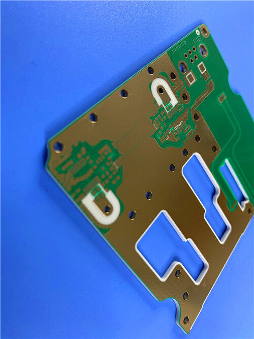
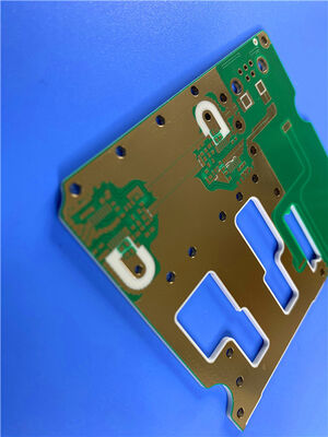
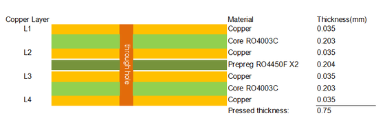
This high-precision 4-layer Rogers RO4003C hybrid PCB is professionally manufactured for high-frequency RF and microwave circuit applications that demand stable electrical performance and high fabrication consistency. Adopting a symmetrical hybrid stackup with 0.203mm RO4003C dielectric on both sides and RO4450F bonding prepreg in the middle, the board achieves a standard lamination pressed thickness of 0.75mm. Every conductive layer is designed with 1oz finished copper thickness, ensuring uniform current conduction and stable high-frequency signal transmission.
In terms of surface finishing and silkscreen, it features green solder mask with black characters on the top layer and plain green solder mask without silkscreen on the bottom layer, paired with 2u” immersion gold plating to deliver excellent oxidation resistance, soldering performance and long-term reliability. Following strict IPC-6012 Class 3 high-reliability manufacturing standards, the product adopts 25μm hole copper thickness and full via resin plugging with electroplated filling technology to eliminate hollow vias, prevent solder overflow and enhance structural tightness. Sized at 98mm × 62mm per piece, this high-frequency PCB supports standardized assembly and batch production, widely suitable for commercial and industrial high-frequency communication equipment.
PCB Specifications
| Parameter Item |
Technical Details |
| Layer Structure |
4-layer hybrid rigid high-frequency PCB |
| Stackup Configuration |
0.203mm RO4003C + RO4450F Prepreg + 0.203mm RO4003C |
| Total Press Thickness |
0.75mm |
| Copper Weight |
1oz finished copper for all layers |
| Surface Treatment |
2u” Immersion Gold |
| Solder Mask & Silkscreen |
Top: Green solder mask with black silkscreen; Bottom: Green solder mask, no silkscreen |
| Board Dimension |
98mm × 62mm (1PCS) |
| Special Process |
Full via resin plugging and electroplated hole filling |
| Hole Copper Thickness |
25μm |
| Quality Standard |
IPC-6012 Class 3 high-reliability grade |

| RO4003C Typical Value |
| Property |
RO4003C |
Direction |
Units |
Condition |
Test Method |
| Dielectric Constant,εProcess |
3.38±0.05 |
Z |
|
10 GHz/23℃ |
IPC-TM-650 2.5.5.5 Clamped Stripline |
| Dielectric Constant,εDesign |
3.55 |
Z |
|
8 to 40 GHz |
Differential Phase Length Method |
| Dissipation Factortan,δ |
0.0027
0.0021 |
Z |
|
10 GHz/23℃
2.5 GHz/23℃ |
IPC-TM-650 2.5.5.5 |
| Thermal Coefficient of ε |
+40 |
Z |
ppm/℃ |
-50℃to 150℃ |
IPC-TM-650 2.5.5.5 |
| Volume Resistivity |
1.7 x 10¹⁰ |
|
MΩ.cm |
COND A |
IPC-TM-650 2.5.17.1 |
| Surface Resistivity |
4.2 x 10⁹ |
|
MΩ |
COND A |
IPC-TM-650 2.5.17.1 |
| Electrical Strength |
31.2(780) |
Z |
Kv/mm(v/mil) |
0.51mm(0.020") |
IPC-TM-650 2.5.6.2 |
| Tensile Modulus |
19,650(2,850)
19,450(2,821) |
X
Y |
MPa(ksi) |
RT |
ASTM D 638 |
| Tensile Strength |
139(20.2)
100(14.5) |
X
Y |
MPa(ksi) |
RT |
ASTM D 638 |
| Flexural Strength |
276
(40) |
|
MPa
(kpsi) |
|
IPC-TM-650 2.4.4 |
| Dimensional Stability |
<0.3 |
X,Y |
mm/m
(mil/inch) |
after etch+E2/150℃ |
IPC-TM-650 2.4.39A |
| Coefficient of Thermal Expansion |
11
14
46 |
X
Y
Z |
ppm/℃ |
-55℃to288℃ |
IPC-TM-650 2.4.41 |
| Tg |
>280 |
|
℃ TMA |
A |
IPC-TM-650 2.4.24.3 |
| Td |
425 |
|
℃ TGA |
|
ASTM D 3850 |
| Thermal Conductivity |
0.71 |
|
W/M/oK |
80℃ |
ASTM C518 |
| Moisture Absorption |
0.06 |
|
% |
48hrs immersion 0.060"
sample Temperature 50℃ |
ASTM D 570 |
| Density |
1.79 |
|
gm/cm3 |
23℃ |
ASTM D 792 |
| Copper Peel Stength |
1.05
(6.0) |
|
N/mm
(pli) |
after solder float 1 oz.
EDC Foil |
IPC-TM-650 2.4.8 |
| Flammability |
N/A |
|
|
|
UL 94 |
| Lead-free Process Compatible |
Yes |
|
|
|
|
Rogers RO4003C Series Material Processing Guidelines
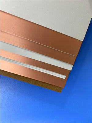
Rogers RO4003C is a premium hydrocarbon ceramic laminate, widely used alongside RO4350B and RO4835 series for high-frequency RF and microwave PCB fabrication. It features stable dielectric performance and excellent universal process compatibility, perfectly suited for standard multilayer PCB manufacturing with RO4400F bonding prepregs. Below are the standardized processing guidelines for RO4003C substrates:
Material Storage Standards
To sustain stable electrical and mechanical properties, fully-clad RO4003C laminates require controlled room-temperature storage between 10°C and 32°C. Adopting a first-in-first-out inventory system and complete batch lot tracking avoids long-term storage degradation, ensuring full quality traceability from raw materials to finished PCB products.
Tooling & Inner Layer Preparation
RO4003C is compatible with mainstream pinned and pinless production tooling. Slotted pins, multi-line tooling and post-etch punching processes are recommended to achieve precise inner-layer alignment. For surface pretreatment, thin-core substrates adopt chemical cleaning, micro-etching and rinsing workflows, while thick-core boards support mechanical scrubbing. The material fits most liquid and dry film photoresists and works seamlessly with conventional FR-4 DES production lines for accurate circuit patterning.
Multilayer Lamination Process
This high-frequency laminate supports standard copper oxide and oxide alternative surface treatment technologies. It is compatible with various thermosetting and thermoplastic adhesive systems, enabling stable, high-reliability multilayer lamination. The standardized bonding process guarantees tight layer integration and consistent structural performance for hybrid high-frequency PCB stacks.
Professional Drilling Specifications
Standard aluminum entry boards and phenolic exit boards are applicable for RO4003C drilling. To ensure optimal hole wall quality, the drilling speed must be limited below 500 SFM. Large-diameter drills require a chip load over 0.002 inches, while small-diameter tools adopt lower chip load settings. Despite slight tool wear during processing, the uniform ceramic particle structure maintains a stable hole wall roughness of 8–25μm, delivering consistent via quality for mass production.


 Your message must be between 20-3,000 characters!
 English