| MOQ: | 1PCS |
| Price: | USD9.99-99.99 |
| Standard Packaging: | Vacuum bags+Cartons |
| Delivery Period: | 8-9 working days |
| Payment Method: | T/T |
| Supply Capacity: | 5000PCS per month |
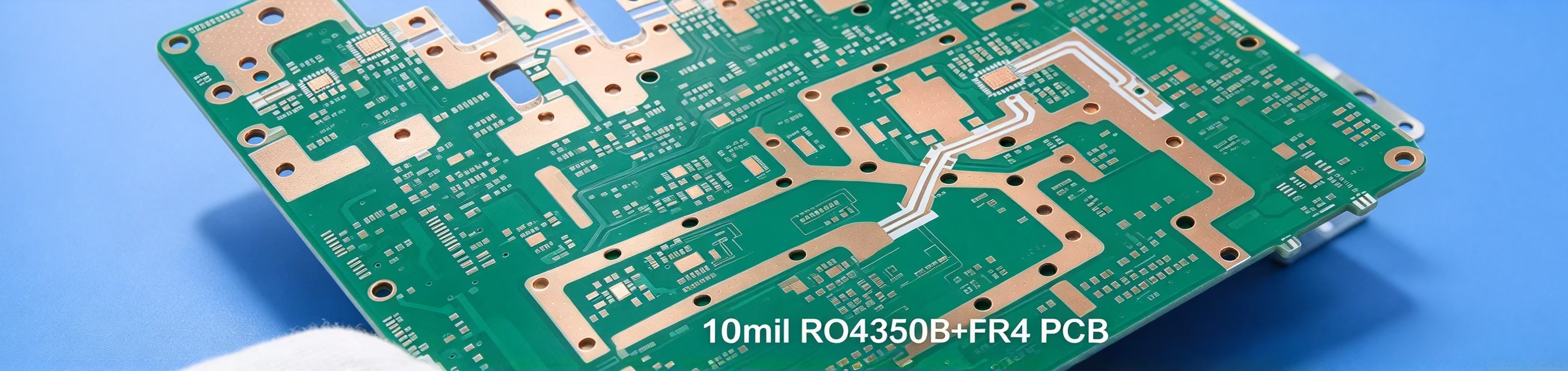
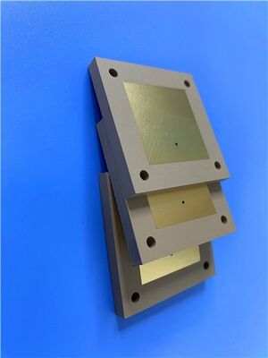
This two-layer microwave circuit substrate adopts Rogers TMM4 as its core dielectric and is finished with ENIG. Green solder mask covers both top and bottom surfaces, and no silkscreen markings are applied on either side. Built for stripline and microstrip layouts, this board maintains stable electrical behaviour while preserving reliable plated-through-hole integrity, making it a solid option for microwave work that calls for consistent performance and broad manufacturing compatibility.
PCB Specifications
| Item | Details |
| Base material | TMM4 |
| Layer count | 2 layers |
| Board dimensions | 70 mm × 110.63 mm per piece, ±0.15 mm |
| Minimum Trace/Space | 6 / 9 mils |
| Minimum Hole Size | 0.5 mm |
| Blind vias | None |
| Finished board thickness | 2 mm |
| Finished Cu weight | 1 oz (1.4 mils) outer layers |
| Via plating thickness | 20 μm |
| Surface finish | ENIG |
| Top Silkscreen | No |
| Bottom Silkscreen | No |
| Top Solder Mask | Green |
| Bottom Solder Mask | Green |
| Pre-shipment check | 100% electrical test |
Gerber RS-274-X is the accepted fabrication file format. Production adheres to IPC-Class-2, and finished boards can be shipped internationally.
PCB Stack-up
This rigid two-layer build consists of a single Rogers TMM4 core sandwiched between two copper foils.
| Layer | Material & Thickness |
| Copper_layer_1 | 35 μm |
| Rogers TMM4 Core | 1.905 mm (75 mil) |
| Copper_layer_2 | 35 μm |
PCB Statistics
| Item | Quantity |
| Components | 53 |
| Total Pads | 87 |
| Thru Hole Pads | 51 |
| Top SMT Pads | 36 |
| Bottom SMT Pads | 0 |
| Vias | 92 |
| Nets | 2 |
![]()
About Rogers TMM4 Substrate
Rogers TMM4 is a thermoset microwave composite loaded with ceramic and hydrocarbon polymer, developed for stripline and microstrip circuits that demand highly reliable plated through holes.
It combines favourable characteristics found in ceramic substrates and conventional PTFE laminates, while removing the need for the specialised handling these materials often require. Built upon thermoset resin, TMM4 maintains structural stability during wire bonding, lowering risks of pad lift or substrate distortion.
The wider TMM family offers a broad selection of dielectric constants and copper cladding options. Its isotropic thermal expansion closely matches copper, supporting robust through-hole construction and predictable post-etch dimensional stability. Its thermal conductivity is roughly twice that of standard PTFE-ceramic blends, assisting heat dissipation from active circuitry. Since these thermoset resins will not soften under heat, wire bonding can proceed without substrate deformation. The base material resists common etchants and solvents used in PCB manufacturing, so nearly all standard PWB processes are compatible. Unlike many PTFE substrates, TMM laminates do not require sodium napthanate treatment before electroless plating.
![]()
Features
Benefits
Typical applications
This TMM4 board works well for microwave projects where steady electrical response and process flexibility carry equal importance. We welcome small prototype runs as well as volume orders for worldwide delivery. Send over your Gerber files for a quote, and feel free to reach out if you would like to confirm lead times for this high-frequency board.
| TMM4 Typical Value | ||||||
| Property | TMM4 | Direction | Units | Condition | Test Method | |
| Dielectric Constant,εProcess | 4.5±0.045 | Z | 10 GHz | IPC-TM-650 2.5.5.5 | ||
| Dielectric Constant,εDesign | 4.7 | - | - | 8GHz to 40 GHz | Differential Phase Length Method | |
| Dissipation Factor (process) | 0.002 | Z | - | 10 GHz | IPC-TM-650 2.5.5.5 | |
| Thermal Coefficient of dielectric constant | +15 | - | ppm/°K | -55℃-125℃ | IPC-TM-650 2.5.5.5 | |
| Insulation Resistance | >2000 | - | Gohm | C/96/60/95 | ASTM D257 | |
| Volume Resistivity | 6 x 10⁸ | - | Mohm.cm | - | ASTM D257 | |
| Surface Resistivity | 1 x 10⁹ | - | Mohm | - | ASTM D257 | |
| Electrical Strength(dielectric strength) | 371 | Z | V/mil | - | IPC-TM-650 method 2.5.6.2 | |
| Thermal Properties | ||||||
| Decompositioin Temperature(Td) | 425 | 425 | ℃TGA | - | ASTM D3850 | |
| Coefficient of Thermal Expansion - X | 16 | X | ppm/K | 0 to 140 ℃ | ASTM E 831 IPC-TM-650, 2.4.41 | |
| Coefficient of Thermal Expansion - Y | 16 | Y | ppm/K | 0 to 140 ℃ | ASTM E 831 IPC-TM-650, 2.4.41 | |
| Coefficient of Thermal Expansion - Z | 21 | Z | ppm/K | 0 to 140 ℃ | ASTM E 831 IPC-TM-650, 2.4.41 | |
| Thermal Conductivity | 0.7 | Z | W/m/K | 80 ℃ | ASTM C518 | |
| Mechanical Properties | ||||||
| Copper Peel Strength after Thermal Stress | 5.7 (1.0) | X,Y | lb/inch (N/mm) | after solder float 1 oz. EDC | IPC-TM-650 Method 2.4.8 | |
| Flexural Strength (MD/CMD) | 15.91 | X,Y | kpsi | A | ASTM D790 | |
| Flexural Modulus (MD/CMD) | 1.76 | X,Y | Mpsi | A | ASTM D790 | |
| Physical Properties | ||||||
| Moisture Absorption (2X2) | 1.27mm (0.050") | 0.07 | - | % | D/24/23 | ASTM D570 |
| 3.18mm (0.125") | 0.18 | |||||
| Specific Gravity | 2.07 | - | - | A | ASTM D792 | |
| Specific Heat Capacity | 0.83 | - | J/g/K | A | Calculated | |
| Lead-Free Process Compatible | YES | - | - | - | - | |
![]()
| MOQ: | 1PCS |
| Price: | USD9.99-99.99 |
| Standard Packaging: | Vacuum bags+Cartons |
| Delivery Period: | 8-9 working days |
| Payment Method: | T/T |
| Supply Capacity: | 5000PCS per month |
This two-layer microwave circuit substrate adopts Rogers TMM4 as its core dielectric and is finished with ENIG. Green solder mask covers both top and bottom surfaces, and no silkscreen markings are applied on either side. Built for stripline and microstrip layouts, this board maintains stable electrical behaviour while preserving reliable plated-through-hole integrity, making it a solid option for microwave work that calls for consistent performance and broad manufacturing compatibility.
PCB Specifications
| Item | Details |
| Base material | TMM4 |
| Layer count | 2 layers |
| Board dimensions | 70 mm × 110.63 mm per piece, ±0.15 mm |
| Minimum Trace/Space | 6 / 9 mils |
| Minimum Hole Size | 0.5 mm |
| Blind vias | None |
| Finished board thickness | 2 mm |
| Finished Cu weight | 1 oz (1.4 mils) outer layers |
| Via plating thickness | 20 μm |
| Surface finish | ENIG |
| Top Silkscreen | No |
| Bottom Silkscreen | No |
| Top Solder Mask | Green |
| Bottom Solder Mask | Green |
| Pre-shipment check | 100% electrical test |
Gerber RS-274-X is the accepted fabrication file format. Production adheres to IPC-Class-2, and finished boards can be shipped internationally.
PCB Stack-up
This rigid two-layer build consists of a single Rogers TMM4 core sandwiched between two copper foils.
| Layer | Material & Thickness |
| Copper_layer_1 | 35 μm |
| Rogers TMM4 Core | 1.905 mm (75 mil) |
| Copper_layer_2 | 35 μm |
PCB Statistics
| Item | Quantity |
| Components | 53 |
| Total Pads | 87 |
| Thru Hole Pads | 51 |
| Top SMT Pads | 36 |
| Bottom SMT Pads | 0 |
| Vias | 92 |
| Nets | 2 |
![]()
About Rogers TMM4 Substrate
Rogers TMM4 is a thermoset microwave composite loaded with ceramic and hydrocarbon polymer, developed for stripline and microstrip circuits that demand highly reliable plated through holes.
It combines favourable characteristics found in ceramic substrates and conventional PTFE laminates, while removing the need for the specialised handling these materials often require. Built upon thermoset resin, TMM4 maintains structural stability during wire bonding, lowering risks of pad lift or substrate distortion.
The wider TMM family offers a broad selection of dielectric constants and copper cladding options. Its isotropic thermal expansion closely matches copper, supporting robust through-hole construction and predictable post-etch dimensional stability. Its thermal conductivity is roughly twice that of standard PTFE-ceramic blends, assisting heat dissipation from active circuitry. Since these thermoset resins will not soften under heat, wire bonding can proceed without substrate deformation. The base material resists common etchants and solvents used in PCB manufacturing, so nearly all standard PWB processes are compatible. Unlike many PTFE substrates, TMM laminates do not require sodium napthanate treatment before electroless plating.
![]()
Features
Benefits
Typical applications
This TMM4 board works well for microwave projects where steady electrical response and process flexibility carry equal importance. We welcome small prototype runs as well as volume orders for worldwide delivery. Send over your Gerber files for a quote, and feel free to reach out if you would like to confirm lead times for this high-frequency board.
| TMM4 Typical Value | ||||||
| Property | TMM4 | Direction | Units | Condition | Test Method | |
| Dielectric Constant,εProcess | 4.5±0.045 | Z | 10 GHz | IPC-TM-650 2.5.5.5 | ||
| Dielectric Constant,εDesign | 4.7 | - | - | 8GHz to 40 GHz | Differential Phase Length Method | |
| Dissipation Factor (process) | 0.002 | Z | - | 10 GHz | IPC-TM-650 2.5.5.5 | |
| Thermal Coefficient of dielectric constant | +15 | - | ppm/°K | -55℃-125℃ | IPC-TM-650 2.5.5.5 | |
| Insulation Resistance | >2000 | - | Gohm | C/96/60/95 | ASTM D257 | |
| Volume Resistivity | 6 x 10⁸ | - | Mohm.cm | - | ASTM D257 | |
| Surface Resistivity | 1 x 10⁹ | - | Mohm | - | ASTM D257 | |
| Electrical Strength(dielectric strength) | 371 | Z | V/mil | - | IPC-TM-650 method 2.5.6.2 | |
| Thermal Properties | ||||||
| Decompositioin Temperature(Td) | 425 | 425 | ℃TGA | - | ASTM D3850 | |
| Coefficient of Thermal Expansion - X | 16 | X | ppm/K | 0 to 140 ℃ | ASTM E 831 IPC-TM-650, 2.4.41 | |
| Coefficient of Thermal Expansion - Y | 16 | Y | ppm/K | 0 to 140 ℃ | ASTM E 831 IPC-TM-650, 2.4.41 | |
| Coefficient of Thermal Expansion - Z | 21 | Z | ppm/K | 0 to 140 ℃ | ASTM E 831 IPC-TM-650, 2.4.41 | |
| Thermal Conductivity | 0.7 | Z | W/m/K | 80 ℃ | ASTM C518 | |
| Mechanical Properties | ||||||
| Copper Peel Strength after Thermal Stress | 5.7 (1.0) | X,Y | lb/inch (N/mm) | after solder float 1 oz. EDC | IPC-TM-650 Method 2.4.8 | |
| Flexural Strength (MD/CMD) | 15.91 | X,Y | kpsi | A | ASTM D790 | |
| Flexural Modulus (MD/CMD) | 1.76 | X,Y | Mpsi | A | ASTM D790 | |
| Physical Properties | ||||||
| Moisture Absorption (2X2) | 1.27mm (0.050") | 0.07 | - | % | D/24/23 | ASTM D570 |
| 3.18mm (0.125") | 0.18 | |||||
| Specific Gravity | 2.07 | - | - | A | ASTM D792 | |
| Specific Heat Capacity | 0.83 | - | J/g/K | A | Calculated | |
| Lead-Free Process Compatible | YES | - | - | - | - | |
![]()