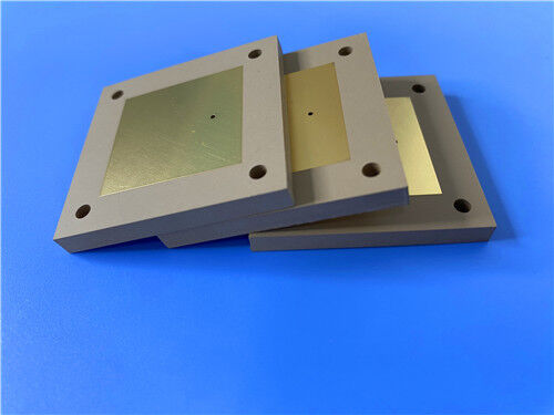
This PCB is a double-sided rigid type fabricated with Rogers TMM10 thermoset microwave material, which integrates PTFE and ceramic substrate advantages while overcoming their mechanical and manufacturing limitations. Compliant with industrial standards, it features 0.5mm finished thickness, 1 oz outer-layer copper weight, and ENEPIG surface finish, ensuring reliable performance for precision microwave and electronic applications.
PCB Details
| Item |
Specification |
| Base material |
TMM10 |
| Layer count |
Double sided |
| Board dimensions |
76mm x 118mm (per piece), +/- 0.15mm |
| Minimum Trace/Space |
4/6 mils |
| Minimum Hole Size |
0.35mm |
| Blind vias |
None |
| Finished board thickness |
0.5mm |
| Finished Cu weight (outer layers) |
1 oz (1.4 mils) |
| Via plating thickness |
20 μm |
| Surface finish |
ENEPIG |
| Top Silkscreen |
White |
| Bottom Silkscreen |
None |
| Top Solder Mask |
Green |
| Bottom Solder Mask |
None |
| Electrical test |
100% electrical test conducted prior to shipment |
PCB Stack-up
This is a 2-layer rigid PCB with the following stack-up structure (from top to bottom):
| Layer Type |
Specification |
| Copper_layer_1 |
35 μm |
| Rogers TMM10 Core |
0.381 mm (15mil) |
| Copper_layer_2 |
35 μm |

Artwork and Quality Standard
The artwork supplied for this PCB complies with the Gerber RS-274-X format, the industry-recognized standard for PCB manufacturing, ensuring seamless compatibility with mainstream fabrication equipment and design software for accurate translation of circuit designs into physical products. Additionally, the PCB adheres to the IPC-Class-2 quality standard, which defines rigorous performance and reliability criteria for electronic components, guaranteeing the product meets the operational requirements of commercial and industrial applications.
Availability
This PCB is available worldwide, covering all major industrial regions and markets. Its global supply capability ensures that customers across different countries and industries can access high-quality, consistent products, with reliable logistics support to fulfill both small-batch prototyping and large-volume production demands in a timely manner.
TMM10 Introduction
Rogers TMM10 thermoset microwave materials integrate the advantages of both PTFE and ceramic-based substrates, while eliminating the limitations associated with their mechanical properties and production techniques. This unique combination makes TMM10 an optimal choice for high-performance microwave and electronic applications, balancing electrical performance, mechanical reliability, and manufacturability.
Benefits of TMM10 Substrate
-Superior mechanical properties resist creep and cold flow, ensuring long-term structural stability in harsh operating environments.
-Excellent resistance to process chemicals, minimizing damage and defects during PCB fabrication processes.
-Eliminates the need for sodium napthanate treatment prior to electroless plating, simplifying the manufacturing process and reducing production costs.
-Based on a thermoset resin system, enabling reliable wire-bonding for high-frequency and high-reliability applications.
Typical Applications
- Chip testers
- Dielectric polarizers
- Satellite communication systems
- GPS antennas and patch antennas
TMM10 High-Frequency Materials
TMM thermoset microwave materials are ceramic, hydrocarbon, and thermoset polymer composites specifically engineered for stripline and microstrip applications requiring high plated through-hole (PTH) reliability. These laminates are offered in a broad selection of dielectric constants and cladding options.
By combining the electrical and mechanical advantages of both ceramic and conventional PTFE microwave circuit laminates, TMM materials eliminate the need for the specialized production techniques typically associated with these products. Notably, TMM laminates do not require sodium naphthanate treatment prior to electroless plating.
These laminates feature an exceptionally low thermal coefficient of dielectric constant, typically below 30 ppm/°C. Their isotropic coefficients of thermal expansion, closely matched to copper, enable highly reliable plated through-holes and low etch shrinkage values. In addition, the thermal conductivity of TMM laminates is approximately double that of traditional PTFE/ceramic laminates, which enhances heat dissipation.
Based on thermoset resins, TMM laminates do not soften when heated. As a result, wire bonding of component leads to circuit traces can be performed without concern for pad lifting or substrate deformation.
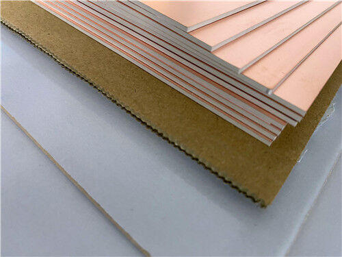
TMM laminates successfully merge the desirable attributes of ceramic substrates with the ease of soft-substrate processing techniques. They are available clad with 0.5 oz/ft² to 2 oz/ft² electrodeposited copper foil, or bonded directly to brass or aluminum plates. Substrate thicknesses range from 0.015 inches to 0.500 inches. The base substrate resists etchants and solvents commonly used in printed circuit production, allowing all standard PWB processes to be used in manufacturing TMM thermoset microwave materials.
| TMM10 Typical Value |
| Property |
TMM10 |
Direction |
Units |
Condition |
Test Method |
| Dielectric Constant,εProcess |
9.20±0.23 |
Z |
|
10 GHz |
IPC-TM-650 2.5.5.5 |
| Dielectric Constant,εDesign |
9.8 |
- |
- |
8GHz to 40 GHz |
Differential Phase Length Method |
| Dissipation Factor (process) |
0.0022 |
Z |
- |
10 GHz |
IPC-TM-650 2.5.5.5 |
| Thermal Coefficient of dielectric constant |
-38 |
- |
ppm/°K |
-55â-125â |
IPC-TM-650 2.5.5.5 |
| Insulation Resistance |
>2000 |
- |
Gohm |
C/96/60/95 |
ASTM D257 |
| Volume Resistivity |
2 x 10⁸ |
- |
Mohm.cm |
- |
ASTM D257 |
| Surface Resistivity |
4 x 10⁷ |
- |
Mohm |
- |
ASTM D257 |
| Electrical Strength(dielectric strength) |
285 |
Z |
V/mil |
- |
IPC-TM-650 method 2.5.6.2 |
| Thermal Properties |
| Decompositioin Temperature(Td) |
425 |
425 |
âTGA |
- |
ASTM D3850 |
| Coefficient of Thermal Expansion - x |
21 |
X |
ppm/K |
0 to 140 â |
ASTM E 831 IPC-TM-650, 2.4.41 |
| Coefficient of Thermal Expansion - Y |
21 |
Y |
ppm/K |
0 to 140 â |
ASTM E 831 IPC-TM-650, 2.4.41 |
| Coefficient of Thermal Expansion - Z |
20 |
Z |
ppm/K |
0 to 140 â |
ASTM E 831 IPC-TM-650, 2.4.41 |
| Thermal Conductivity |
0.76 |
Z |
W/m/K |
80 â |
ASTM C518 |
| Mechanical Properties |
| Copper Peel Strength after Thermal Stress |
5.0 (0.9) |
X,Y |
lb/inch (N/mm) |
after solder float 1 oz. EDC |
IPC-TM-650 Method 2.4.8 |
| Flexural Strength (MD/CMD) |
13.62 |
X,Y |
kpsi |
A |
ASTM D790 |
| Flexural Modulus (MD/CMD) |
1.79 |
X,Y |
Mpsi |
A |
ASTM D790 |
| Physical Properties |
| Moisture Absorption (2X2) |
1.27mm (0.050") |
0.09 |
- |
% |
D/24/23 |
ASTM D570 |
| 3.18mm (0.125") |
0.2 |
| Specific Gravity |
2.77 |
- |
- |
A |
ASTM D792 |
| Specific Heat Capacity |
0.74 |
- |
J/g/K |
A |
Calculated |
| Lead-Free Process Compatible |
YES |
- |
- |
- |
- |
TMM10 Substrate Available
| Standard Thicknesses Standard Panel Sizes Standard Claddings |
|
0.015” (0.381mm) +/- 0.0015”
0.025” (0.635mm) +/- 0.0015”
0.030” (0.762mm) +/- 0.0015”
0.050” (1.270mm) +/- 0.0015”
0.060” (1.524mm) +/- 0.0015”
0.075” (1.900mm) +/- 0.0015”
|
0. 100”(2.500mm) +/- 0.0015”
0. 125”(3. 175mm) +/- 0.0015”
0. 150”(3.810mm) +/- 0.0015”
0.200”(5.080mm) +/- 0.0015”
0.250”(6.350mm) +/- 0.0015”
0.500”(12.70mm) +/- 0.0015”
|
18”X 12”(457mm X 305mm)
18”X 24”(457mm X 610mm)
*Additional panel sizes available
|
Electrodeposited Copper Foil ½ oz. (18µm) HH/HH
1 oz. (35µm) H1/H1
*Additional claddings such as heavy metal and unclad are available
|

 Your message must be between 20-3,000 characters!
 English