| MOQ: | 1PCS |
| Price: | USD9.99-99.99 |
| Standard Packaging: | Vacuum bags+Cartons |
| Delivery Period: | 8-9 working days |
| Payment Method: | T/T |
| Supply Capacity: | 5000PCS per month |
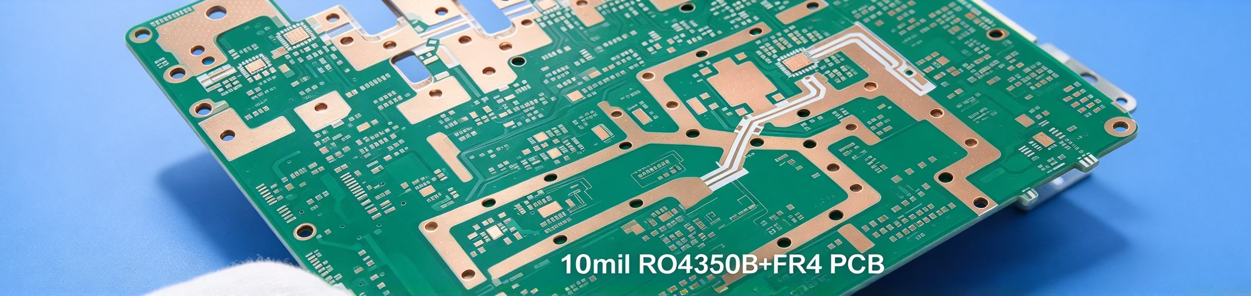
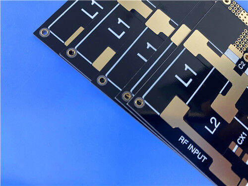
This 2-layer rigid high-frequency PCB is built using Wangling F4BME300 PTFE composite laminate with immersion gold finishing. It carries white silkscreen and black solder mask only on the top side, while the bottom side has neither marking nor solder mask. Delivering consistent high-frequency signal behaviour, this board suits microwave and RF modules, radar units, phase shifters, power dividers, couplers, feed networks, phased array antennas, satellite links and base station antenna systems.
PCB Specifications
| Item | Details |
| Layer Type | 2-layer rigid PCB |
| Base Material | Wangling F4BME300 PTFE composite laminate with RTF copper foil |
| Single Board Dimension | 35.65 mm × 68.95 mm, ±0.15 mm tolerance |
| Finished Board Thickness | 0.2 mm |
| Minimum Trace / Space | 6 / 9 mils |
| Minimum Hole Size | 0.3 mm |
| Outer Copper Weight | 1 oz (1.4 mils) |
| Via Plating Thickness | 20 μm |
| Surface Finish | Immersion gold |
| Silkscreen | Top: White; Bottom: None |
| Solder Mask | Top: Black; Bottom: None |
| Pre-Shipment Validation | 100% electrical test |
We accept Gerber RS-274-X as the standard file format. All boards follow IPC-Class-2 requirements and can be shipped to customers worldwide.
PCB Stack-up
This simple double-sided construction uses one F4BME300 core sandwiched between two copper layers.
| Layer | Material & Thickness |
| Copper Layer 1 | 35 μm |
| Core Substrate | F4BME300, 1.0 mm (39.37 mil) |
| Copper Layer 2 | 35 μm |
Layout Statistics
| Item | Quantity |
| Total Components | 37 |
| Total Pads | 29 |
| Thru-hole Pads | 18 |
| Top-Side SMT Pads | 11 |
| Bottom-Side SMT Pads | 0 |
| Vias | 27 |
| Nets | 6 |
![]()
About F4BME300 Laminate
Wangling F4BME300 is a PTFE glass-cloth copper-clad laminate. It is made from woven fiberglass cloth, PTFE resin and PTFE film, mixed carefully and pressed under tight process control. Compared with the older F4B grade, it delivers better electrical behaviour: wider usable DK range, lower dielectric loss, higher insulation resistance and more consistent performance. It serves as a practical drop-in replacement for equivalent imported high-frequency substrates.
F4BME300 comes with reverse-treated foil, or RTF copper. This foil brings strong PIM performance, allows finer, more predictable line definition and cuts down conductor loss. Its dielectric constant is tuned by adjusting the ratio between PTFE and fiberglass. More fiberglass pushes the DK higher while improving dimensional stability, lowering thermal expansion and reducing temperature drift, at the cost of a small rise in dielectric loss.
![]()
Product Features
Typical Applications
Key Electrical & Thermal Properties
| Product Technical Parameters | Product Model & Data Sheet | |||
| Product Features | Test Conditions | Unit | F4BME300 | |
| Dielectric Constant (Typical) | 10GHz | / | 3.0 | |
| Dielectric Constant Tolerance | / | / | ±0.06 | |
| Loss Tangent (Typical) | 10GHz | / | 0.0017 | |
| 20GHz | / | 0.0025 | ||
| Dielectric Constant Temperature Coefficient | -55ºC~150ºC | PPM/℃ | -80 | |
| Peel Strength | 1 OZ F4BM | N/mm | >1.8 | |
| 1 OZ F4BME | N/mm | >1.6 | ||
| Volume Resistivity | Standard Condition | MΩ.cm | ≥6×10^6 | |
| Surface Resistivity | Standard Condition | MΩ | ≥1×10^6 | |
| Electrical Strength (Z direction) | 5KW,500V/s | KV/mm | >30 | |
| Breakdown Voltage (XY direction) | 5KW,500V/s | KV | >36 | |
| Coefficientof Thermal Expansion | XY direction | -55 º~288ºC | ppm/ºC | 12, 15 |
| Z direction | -55 º~288ºC | ppm/ºC | 95 | |
| Thermal Stress | 260℃, 10s,3 times | No delamination | ||
| Water Absorption | 20±2℃, 24 hours | % | ≤0.08 | |
| Density | Room Temperature | g/cm3 | 2.29 | |
| Long-Term Operating Temperature | High-Low Temperature Chamber | ℃ | -55~+260 | |
| Thermal Conductivity | Z direction | W/(M.K) | 0.42 | |
| PIM | Only applicable to F4BME | dBc | ≤-159 | |
| Flammability | / | UL-94 | V-0 | |
| Material Composition | / | / | PTFE, Fiberglass Cloth F4BM paired with ED copper foil, F4BME paired with reverse-treated (RTF) copper foil. |
|
For teams sourcing reliable RF boards for passive microwave hardware, this two-layer PCB built on F4BME300 delivers stable signal integrity and low PIM across wide temperature ranges, manufactured to IPC-Class-2 standards. We support small prototype batches as well as larger volume runs with global delivery. Submit your Gerber files to receive a formal quotation. Reach out if you would like lead time and pricing details for your radar, satellite or base station projects.
![]()
![]()
| MOQ: | 1PCS |
| Price: | USD9.99-99.99 |
| Standard Packaging: | Vacuum bags+Cartons |
| Delivery Period: | 8-9 working days |
| Payment Method: | T/T |
| Supply Capacity: | 5000PCS per month |
This 2-layer rigid high-frequency PCB is built using Wangling F4BME300 PTFE composite laminate with immersion gold finishing. It carries white silkscreen and black solder mask only on the top side, while the bottom side has neither marking nor solder mask. Delivering consistent high-frequency signal behaviour, this board suits microwave and RF modules, radar units, phase shifters, power dividers, couplers, feed networks, phased array antennas, satellite links and base station antenna systems.
PCB Specifications
| Item | Details |
| Layer Type | 2-layer rigid PCB |
| Base Material | Wangling F4BME300 PTFE composite laminate with RTF copper foil |
| Single Board Dimension | 35.65 mm × 68.95 mm, ±0.15 mm tolerance |
| Finished Board Thickness | 0.2 mm |
| Minimum Trace / Space | 6 / 9 mils |
| Minimum Hole Size | 0.3 mm |
| Outer Copper Weight | 1 oz (1.4 mils) |
| Via Plating Thickness | 20 μm |
| Surface Finish | Immersion gold |
| Silkscreen | Top: White; Bottom: None |
| Solder Mask | Top: Black; Bottom: None |
| Pre-Shipment Validation | 100% electrical test |
We accept Gerber RS-274-X as the standard file format. All boards follow IPC-Class-2 requirements and can be shipped to customers worldwide.
PCB Stack-up
This simple double-sided construction uses one F4BME300 core sandwiched between two copper layers.
| Layer | Material & Thickness |
| Copper Layer 1 | 35 μm |
| Core Substrate | F4BME300, 1.0 mm (39.37 mil) |
| Copper Layer 2 | 35 μm |
Layout Statistics
| Item | Quantity |
| Total Components | 37 |
| Total Pads | 29 |
| Thru-hole Pads | 18 |
| Top-Side SMT Pads | 11 |
| Bottom-Side SMT Pads | 0 |
| Vias | 27 |
| Nets | 6 |
![]()
About F4BME300 Laminate
Wangling F4BME300 is a PTFE glass-cloth copper-clad laminate. It is made from woven fiberglass cloth, PTFE resin and PTFE film, mixed carefully and pressed under tight process control. Compared with the older F4B grade, it delivers better electrical behaviour: wider usable DK range, lower dielectric loss, higher insulation resistance and more consistent performance. It serves as a practical drop-in replacement for equivalent imported high-frequency substrates.
F4BME300 comes with reverse-treated foil, or RTF copper. This foil brings strong PIM performance, allows finer, more predictable line definition and cuts down conductor loss. Its dielectric constant is tuned by adjusting the ratio between PTFE and fiberglass. More fiberglass pushes the DK higher while improving dimensional stability, lowering thermal expansion and reducing temperature drift, at the cost of a small rise in dielectric loss.
![]()
Product Features
Typical Applications
Key Electrical & Thermal Properties
| Product Technical Parameters | Product Model & Data Sheet | |||
| Product Features | Test Conditions | Unit | F4BME300 | |
| Dielectric Constant (Typical) | 10GHz | / | 3.0 | |
| Dielectric Constant Tolerance | / | / | ±0.06 | |
| Loss Tangent (Typical) | 10GHz | / | 0.0017 | |
| 20GHz | / | 0.0025 | ||
| Dielectric Constant Temperature Coefficient | -55ºC~150ºC | PPM/℃ | -80 | |
| Peel Strength | 1 OZ F4BM | N/mm | >1.8 | |
| 1 OZ F4BME | N/mm | >1.6 | ||
| Volume Resistivity | Standard Condition | MΩ.cm | ≥6×10^6 | |
| Surface Resistivity | Standard Condition | MΩ | ≥1×10^6 | |
| Electrical Strength (Z direction) | 5KW,500V/s | KV/mm | >30 | |
| Breakdown Voltage (XY direction) | 5KW,500V/s | KV | >36 | |
| Coefficientof Thermal Expansion | XY direction | -55 º~288ºC | ppm/ºC | 12, 15 |
| Z direction | -55 º~288ºC | ppm/ºC | 95 | |
| Thermal Stress | 260℃, 10s,3 times | No delamination | ||
| Water Absorption | 20±2℃, 24 hours | % | ≤0.08 | |
| Density | Room Temperature | g/cm3 | 2.29 | |
| Long-Term Operating Temperature | High-Low Temperature Chamber | ℃ | -55~+260 | |
| Thermal Conductivity | Z direction | W/(M.K) | 0.42 | |
| PIM | Only applicable to F4BME | dBc | ≤-159 | |
| Flammability | / | UL-94 | V-0 | |
| Material Composition | / | / | PTFE, Fiberglass Cloth F4BM paired with ED copper foil, F4BME paired with reverse-treated (RTF) copper foil. |
|
For teams sourcing reliable RF boards for passive microwave hardware, this two-layer PCB built on F4BME300 delivers stable signal integrity and low PIM across wide temperature ranges, manufactured to IPC-Class-2 standards. We support small prototype batches as well as larger volume runs with global delivery. Submit your Gerber files to receive a formal quotation. Reach out if you would like lead time and pricing details for your radar, satellite or base station projects.
![]()
![]()