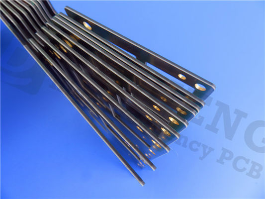
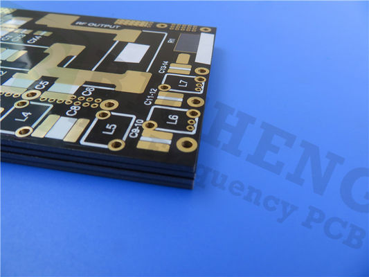
Introducing our newly shipped PCB on RT/duroid 5880 laminates. RT/duroid 5880 laminaets, combines PTFE composites with glass microfibers to deliver exceptional performance in high-frequency and broadband applications. With its low dielectric constant (Dk) and low dielectric loss, this PCB is designed to meet the most demanding requirements of modern electronic systems.
The RT/duroid 5880 laminates feature a dielectric constant of 2.2 with a tight tolerance of 0.02 at 10 GHz/23°C. This ensures consistent and reliable signal transmission, allowing for precise and accurate high-frequency operation. With a dissipation factor of 0.0009 at 10GHz, this PCB minimizes energy loss, maximizing signal integrity.
Thermal stability is a key factor in high-frequency applications, and the RT/duroid 5880 excels in this aspect. It boasts a temperature coefficient of dielectric constant (TCDk) of -125 ppm/°C, ensuring stable performance across varying temperature conditions. Its low moisture absorption of 0.02% contributes to its exceptional reliability, even in high-moisture environments.
| RT/duroid 5880 Typical Value |
| Property |
RT/duroid 5880 |
Direction |
Units |
Condition |
Test Method |
| Dielectric Constant,εProcess |
2.20
2.20±0.02 spec. |
Z |
N/A |
C24/23/50
C24/23/50 |
1 MHz IPC-TM-650 2.5.5.3
10 GHz IPC-TM 2.5.5.5 |
| Dielectric Constant,εDesign |
2.2 |
Z |
N/A |
8GHz to 40 GHz |
Differential Phase Length Method |
| Dissipation Factor,tanδ |
0.0004
0.0009 |
Z |
N/A |
C24/23/50
C24/23/50 |
1 MHz IPC-TM-650 2.5.5.3
10 GHz IPC-TM 2.5.5.5 |
| Thermal Coefficient of ε |
-125 |
Z |
ppm/℃ |
-50℃to 150℃ |
IPC-TM-650 2.5.5.5 |
| Volume Resistivity |
2 x 10⁷ |
Z |
Mohm cm |
C/96/35/90 |
ASTM D 257 |
| Surface Resistivity |
3 x 10⁷ |
Z |
Mohm |
C/96/35/90 |
ASTM D 257 |
| Specific Heat |
0.96(0.23) |
N/A |
j/g/k
(cal/g/c) |
N/A |
Calculated |
| Tensile Modulus |
Test at 23℃ |
Test at 100℃ |
N/A |
MPa(kpsi) |
A |
ASTM D 638 |
| 1070(156) |
450(65) |
X |
| 860(125) |
380(55) |
Y |
| Ultimate Stress |
29(4.2) |
20(2.9) |
X |
| 27(3.9) |
18(2.6) |
Y |
| Ultimate Strain |
6 |
7.2 |
X |
% |
| 4.9 |
5.8 |
Y |
| Compressive Modulus |
710(103) |
500(73) |
X |
MPa(kpsi) |
A |
ASTM D 695 |
| 710(103) |
500(73) |
Y |
| 940(136) |
670(97) |
Z |
| Ultimate Stress |
27(3.9) |
22(3.2) |
X |
| 29(5.3) |
21(3.1) |
Y |
| 52(7.5) |
43(6.3) |
Z |
| Ultimate Strain |
8.5 |
8.4 |
X |
% |
| 7.7 |
7.8 |
Y |
| 12.5 |
17.6 |
Z |
| Moisture Absorption |
0.02 |
N/A |
% |
0.62"(1.6mm) D48/50 |
ASTM D 570 |
| Thermal Conductivity |
0.2 |
Z |
W/m/k |
80℃ |
ASTM C 518 |
| Coefficient of Thermal Expansion |
31
48
237 |
X
Y
Z |
ppm/℃ |
0-100℃ |
IPC-TM-650 2.4.41 |
| Td |
500 |
N/A |
℃ TGA |
N/A |
ASTM D 3850 |
| Density |
2.2 |
N/A |
gm/cm3 |
N/A |
ASTM D 792 |
| Copper Peel |
31.2(5.5) |
N/A |
Pli(N/mm) |
1oz(35mm)EDC foil
after solder float |
IPC-TM-650 2.4.8 |
| Flammability |
V-0 |
N/A |
N/A |
N/A |
UL 94 |
| Lead-free Process Compatible |
Yes |
N/A |
N/A |
N/A |
N/A |
The RT/duroid 5880 PCB offers uniform electrical properties over a wide frequency range, making it suitable for various high-frequency applications. Its isotropic nature allows for easy cutting, shaping, and machining, enabling efficient and precise manufacturing processes. The material is resistant to solvents and reagents used in etching or plating edges and holes, further enhancing its durability and longevity.
With a well-established reputation, the RT/duroid 5880 is a trusted and proven material in the industry. It provides the lowest electrical loss among reinforced PTFE materials, ensuring optimal performance and signal integrity.

The PCB stackup consists of a 2-layer rigid PCB with copper layers of 35 μm on each side and an RT/duroid 5880 core thickness of 0.127 mm (5mil). With a board dimension of 35mm x 70 mm, it offers a compact and efficient layout for your designs.
This PCB supports intricate and precise circuit designs with a minimum trace/space of 5/5 mils and a minimum hole size of 0.4mm. It has a finished board thickness of 0.2mm and a finished copper weight of 1oz (1.4 mils) on the outer layers, ensuring durability and reliability.
The RT/duroid 5880 PCB undergoes rigorous testing, with 100% electrical testing performed prior to shipment, meeting IPC-Class-2 quality standards. It is available worldwide, ensuring easy access to this high-performance solution.
With 7 components, 18 total pads, 9 thru-hole pads, 9 top SMT pads, and 6 vias, the RT/duroid 5880 PCB offers flexibility and versatility for your designs. It finds applications in various fields, including commercial airline broadband antennas, microstrip and stripline circuits, millimeter wave applications, radar systems, guidance systems, and point-to-point digital radio antennas.
Choose the RT/duroid 5880 PCB to unlock the full potential of high-frequency performance in your advanced applications.

 Your message must be between 20-3,000 characters!
 English