| MOQ: | 1PCS |
| Price: | USD9.99-99.99 |
| Standard Packaging: | Vacuum bags+Cartons |
| Delivery Period: | 8-9 working days |
| Payment Method: | T/T |
| Supply Capacity: | 5000PCS per month |
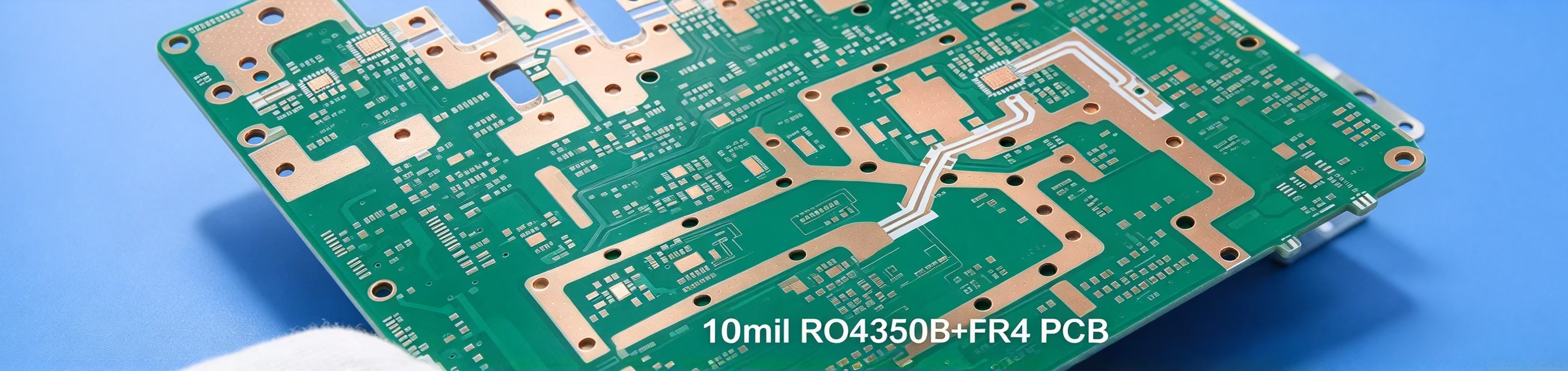
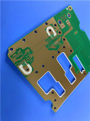
This two-layer rigid PCB is built on Rogers RO4535 high-frequency hydrocarbon laminate with immersion silver finish. Green solder mask covers both sides; white silkscreen appears only on the top, with no marking on the reverse. It suits antenna hardware for cellular and WiMAX communication networks. Every finished PCB passes full electrical testing before shipment, manufactured to IPC-Class-2 and available for delivery across the globe.
PCB Specifications
| Section | Details |
| Based material | Rogers RO4535 |
| Board dimensions | 63 mm × 79.5 mm, ±0.15 mm |
| Minimum Trace / Space | 4 / 6 mils |
| Minimum Hole Size | 0.25 mm |
| Blind vias | None |
| Finished board thickness | 1.6 mm |
| Outer finished copper | 1 oz (1.4 mils) |
| Via plating thickness | 20 μm |
| Surface finish | Immersion Silver |
| Top silkscreen | White |
| Bottom silkscreen | None |
| Top solder mask | Green |
| Bottom solder mask | Green |
| Pre-shipment test | 100% electrical test |
The artwork is supplied in Gerber RS-274-X format; Each PCB follow IPC-Class-2 quality standard and can be shipped worldwide.
Stack-up
This build relies on one solid Rogers RO4535 core sandwiched between two copper layers. There are no extra lamination stages or embedded dielectrics, keeping the electrical response steady and straightforward for regular production runs.
| Layer | Specification |
| Copper_layer_1 | 35 μm |
| Core | Rogers RO4535, 1.524 mm (60 mil) |
| Copper_layer_2 | 35 μm |
PCB Statistics
These counts are pulled straight from the submitted Gerber output. They offer a quick view of pads, vias and net quantities used to review manufacturability.
| Item | Quantity |
| Components | 31 |
| Total Pads | 29 |
| Thru Hole Pads | 17 |
| Top SMT Pads | 12 |
| Bottom SMT Pads | 0 |
| Vias | 6 |
| Nets | 2 |
![]()
Rogers RO4535 Laminate Introduction
Rogers RO4535 laminates balance cost and performance, made specifically for antenna markets. It extends the proven RO4000 family into antenna applications. As a ceramic-filled, glass-reinforced hydrocarbon material, it delivers stable dielectric constant, low signal loss and strong passive intermodulation performance ideal for microstrip antennas deployed in mobile infrastructure.
It works well alongside standard FR-4 and high-temperature lead-free soldering processes. Unlike traditional PTFE laminates, it does not call for special pre-treatment before plated through-hole processing. It serves as an affordable alternative to older PTFE antenna materials, helping to balance cost and performance for antenna hardware. Versions built with Rogers’ RoHS-compliant flame retardant technology can also meet UL94 V-0 where required.
![]()
| Property | RO4535 | Direction | Units | Condition | Test Method |
| Dielectric Constant, er Process | 3.44 ± 0.08 | Z | - | 10 GHz/23℃ 2.5 GHz | IPC-TM-650,2.5.5.5 |
| Dissipation Factor | 0.0032 | Z | - | 2.5 GHz/23℃ | IPC-TM-650, 2.5.5.5 |
| 0.0037 | 10 GHz/23℃ | ||||
| PIM (Typical) | -157 | - | dBc | Reflected 43 dBm swept tones | Summitek 1900b PIM Analyzer |
| Dielectric Strength | >500 | Z | V/mil | 0.51 mm | IPC-TM-650, 2.5.6.2 |
| Dimensional Stability | <0.5 | X,Y | mm/m (mils/inch) | after etch | IPC-TM-650, 2.4.39A |
| Coefficient of Thermal Expansion | 16 | X | ppm/℃ | -55 to 288℃ | IPC-TM-650, 2.4.41 |
| 17 | Y | ||||
| 50 | Z | ||||
| Thermal Conductivity | 0.6 | - | W/(m.K) | 80℃ | ASTM C518 |
| Moisture Absorption | 0.09 | - | % | D48/50 | IPC-TM-650, 2.6.2.1 ASTM D570 |
| Tg | >280 | - | ℃ TMA | A | IPC-TM-650, 2.4.24.3 |
| Density | 1.9 | - | gm/cm3 | - | ASTM D792 |
| Copper Peel Strength | 5.1 (0.9) | - | lbs/in (N/mm) | 1 oz. EDC post solder float | IPC-TM-650, 2.4.8 |
| Flammability | V-0 | - | - | - | UL 94 |
| Lead-Free Process Compatible | Yes | - | - | - | - |
Features
Benefits
Applications
Boasting dependable low-loss transmission, favourable PIM behaviour and compatibility with standard circuit fabrication workflows, this RO4535 PCB acts as a practical, cost-conscious solution for microstrip antennas within cellular base stations and WiMAX communication infrastructure. It removes many of the processing hurdles common to PTFE substrates while maintaining consistent radio frequency performance over long service cycles. If you send over your Gerber files, we can work up a quote based on the provided artwork and production requirements.
RO4535 Substrate Available
| Standard Thicknesses | Standard Panel Sizes: | Standard Claddings |
| RO4535 | 24”X18”(610X457 mm) | Electrodeposited Copper Foil |
| 0.020”(0.508mm)+/-0.0015” | 24”X21”(610X533 mm) | ½ oz. (18µm) HH/HH |
| 0.030”(0.762mm)+/-0.0015” | 24”X36”(610X915 mm) | 1 oz. (35µm) H1/H1 |
| 0.060”(1.524mm)+/-0.0040” | 48”X36”(1219X915mm) |
![]()
| MOQ: | 1PCS |
| Price: | USD9.99-99.99 |
| Standard Packaging: | Vacuum bags+Cartons |
| Delivery Period: | 8-9 working days |
| Payment Method: | T/T |
| Supply Capacity: | 5000PCS per month |
This two-layer rigid PCB is built on Rogers RO4535 high-frequency hydrocarbon laminate with immersion silver finish. Green solder mask covers both sides; white silkscreen appears only on the top, with no marking on the reverse. It suits antenna hardware for cellular and WiMAX communication networks. Every finished PCB passes full electrical testing before shipment, manufactured to IPC-Class-2 and available for delivery across the globe.
PCB Specifications
| Section | Details |
| Based material | Rogers RO4535 |
| Board dimensions | 63 mm × 79.5 mm, ±0.15 mm |
| Minimum Trace / Space | 4 / 6 mils |
| Minimum Hole Size | 0.25 mm |
| Blind vias | None |
| Finished board thickness | 1.6 mm |
| Outer finished copper | 1 oz (1.4 mils) |
| Via plating thickness | 20 μm |
| Surface finish | Immersion Silver |
| Top silkscreen | White |
| Bottom silkscreen | None |
| Top solder mask | Green |
| Bottom solder mask | Green |
| Pre-shipment test | 100% electrical test |
The artwork is supplied in Gerber RS-274-X format; Each PCB follow IPC-Class-2 quality standard and can be shipped worldwide.
Stack-up
This build relies on one solid Rogers RO4535 core sandwiched between two copper layers. There are no extra lamination stages or embedded dielectrics, keeping the electrical response steady and straightforward for regular production runs.
| Layer | Specification |
| Copper_layer_1 | 35 μm |
| Core | Rogers RO4535, 1.524 mm (60 mil) |
| Copper_layer_2 | 35 μm |
PCB Statistics
These counts are pulled straight from the submitted Gerber output. They offer a quick view of pads, vias and net quantities used to review manufacturability.
| Item | Quantity |
| Components | 31 |
| Total Pads | 29 |
| Thru Hole Pads | 17 |
| Top SMT Pads | 12 |
| Bottom SMT Pads | 0 |
| Vias | 6 |
| Nets | 2 |
![]()
Rogers RO4535 Laminate Introduction
Rogers RO4535 laminates balance cost and performance, made specifically for antenna markets. It extends the proven RO4000 family into antenna applications. As a ceramic-filled, glass-reinforced hydrocarbon material, it delivers stable dielectric constant, low signal loss and strong passive intermodulation performance ideal for microstrip antennas deployed in mobile infrastructure.
It works well alongside standard FR-4 and high-temperature lead-free soldering processes. Unlike traditional PTFE laminates, it does not call for special pre-treatment before plated through-hole processing. It serves as an affordable alternative to older PTFE antenna materials, helping to balance cost and performance for antenna hardware. Versions built with Rogers’ RoHS-compliant flame retardant technology can also meet UL94 V-0 where required.
![]()
| Property | RO4535 | Direction | Units | Condition | Test Method |
| Dielectric Constant, er Process | 3.44 ± 0.08 | Z | - | 10 GHz/23℃ 2.5 GHz | IPC-TM-650,2.5.5.5 |
| Dissipation Factor | 0.0032 | Z | - | 2.5 GHz/23℃ | IPC-TM-650, 2.5.5.5 |
| 0.0037 | 10 GHz/23℃ | ||||
| PIM (Typical) | -157 | - | dBc | Reflected 43 dBm swept tones | Summitek 1900b PIM Analyzer |
| Dielectric Strength | >500 | Z | V/mil | 0.51 mm | IPC-TM-650, 2.5.6.2 |
| Dimensional Stability | <0.5 | X,Y | mm/m (mils/inch) | after etch | IPC-TM-650, 2.4.39A |
| Coefficient of Thermal Expansion | 16 | X | ppm/℃ | -55 to 288℃ | IPC-TM-650, 2.4.41 |
| 17 | Y | ||||
| 50 | Z | ||||
| Thermal Conductivity | 0.6 | - | W/(m.K) | 80℃ | ASTM C518 |
| Moisture Absorption | 0.09 | - | % | D48/50 | IPC-TM-650, 2.6.2.1 ASTM D570 |
| Tg | >280 | - | ℃ TMA | A | IPC-TM-650, 2.4.24.3 |
| Density | 1.9 | - | gm/cm3 | - | ASTM D792 |
| Copper Peel Strength | 5.1 (0.9) | - | lbs/in (N/mm) | 1 oz. EDC post solder float | IPC-TM-650, 2.4.8 |
| Flammability | V-0 | - | - | - | UL 94 |
| Lead-Free Process Compatible | Yes | - | - | - | - |
Features
Benefits
Applications
Boasting dependable low-loss transmission, favourable PIM behaviour and compatibility with standard circuit fabrication workflows, this RO4535 PCB acts as a practical, cost-conscious solution for microstrip antennas within cellular base stations and WiMAX communication infrastructure. It removes many of the processing hurdles common to PTFE substrates while maintaining consistent radio frequency performance over long service cycles. If you send over your Gerber files, we can work up a quote based on the provided artwork and production requirements.
RO4535 Substrate Available
| Standard Thicknesses | Standard Panel Sizes: | Standard Claddings |
| RO4535 | 24”X18”(610X457 mm) | Electrodeposited Copper Foil |
| 0.020”(0.508mm)+/-0.0015” | 24”X21”(610X533 mm) | ½ oz. (18µm) HH/HH |
| 0.030”(0.762mm)+/-0.0015” | 24”X36”(610X915 mm) | 1 oz. (35µm) H1/H1 |
| 0.060”(1.524mm)+/-0.0040” | 48”X36”(1219X915mm) |
![]()